
Architecture for thermostat control during peak intervals

a thermostat and peak interval technology, applied in the field of thermostat control during peak intervals, can solve the problems of no easy, automated way, and physical limitations on the amount/ability to push excess power generated from on-site solar, and achieve the effect of reducing the total instantaneous energy usage rate, and reducing the energy usage rate of the hvac system

Active Publication Date: 2017-12-21
GOOGLE LLC
View PDF13 Cites 9 Cited by
  • Summary
  • Abstract
  • Description
  • Claims
  • Application Information

AI Technical Summary

Benefits of technology

The patent describes a thermostat that can control the temperature of a structure using a stored setpoint schedule and temperature sensors. The thermostat can also receive an indication that the structure is using more energy than expected and adjust the setpoint schedule to reduce energy usage. The technical effect of this invention is to provide a more efficient and effective way to control the temperature of a structure, reducing energy usage and improving user comfort.

Problems solved by technology

In other cases, there are regulations or physical limitations on the amount / ability to push excess power generated from on-site solar, for example back onto the broader electrical grid, either for monetization or relief.
In these circumstances, there is no easy, automated way, for a customer to manage for these peaks and the customer can end up with materially negative effects to their utility bill.
The problem is that customers have no easy or automated way of changing their consumption pattern to adapt to peak demand charges through the course of a day.
Typically, users have no idea when their total household power consumption is about to cross an instantaneous threshold that will incur extra charges.
Because demand charges are based on total instantaneous household consumption, there is no one thing that consumers can do to automatically reduce power consumption in real time as would be required to avoid extra cost.

Method used


Image

  • Architecture for thermostat control during peak intervals
  • Architecture for thermostat control during peak intervals
  • Architecture for thermostat control during peak intervals

Examples


Embodiment Construction

[0031]The subject matter of this patent specification relates to the subject matter of the following commonly assigned application, filed on the same day as the present application, which is incorporated by reference herein:[0032]U.S. patent application Ser. No. ______, (Atty. Dkt. No. 094021-1009870), filed on Jun. 20, 2016, entitled “Architecture for Thermostat Control during Time-of-Use Intervals,” by Greene et al.

The Smart-Home Environment

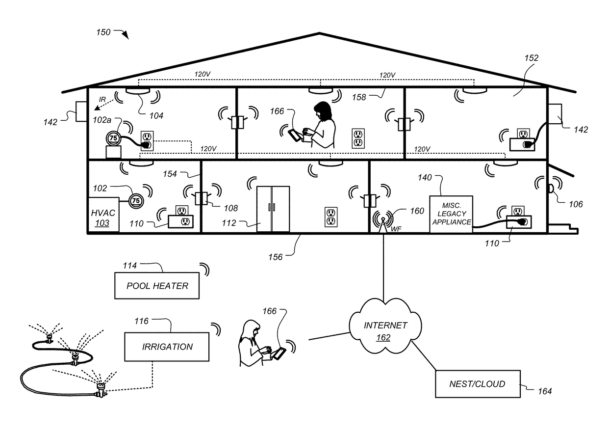
[0033]A detailed description of the inventive body of work is provided herein. While several embodiments are described, it should be understood that the inventive body of work is not limited to any one embodiment, but instead encompasses numerous alternatives, modifications, and equivalents. In addition, while numerous specific details are set forth in the following description in order to provide a thorough understanding of the inventive body of work, some embodiments can be practiced without some or all of these details. Moreover, for the pur...


PUM


Abstract

A thermostat may include one or more memory devices comprising a stored setpoint schedule, one or more temperature sensors configured to provide temperature sensor measurements, and a processing system configured to be in operative communication the one or more memory devices to determine a setpoint temperature, and in still further operative communication with a heating, ventilation, and air conditioning (HVAC) system to control the HVAC system based at least in part on the setpoint temperature and the temperature sensor measurements. The processing system may be configured to control the HVAC system by receiving an indication that a total instantaneous energy usage rate for a structure in which the thermostat is installed is projected to exceed a threshold amount; and altering the stored setpoint schedule to reduce an energy usage rate of the HVAC system.

Description

BACKGROUND[0001]Some residential rate structures allow for one-time charges to be levied on residential customers when their peak power consumption exceeds certain thresholds in a given time window over monthly cycle. Residential demand charges can often be based on the highest 15-minute average usage recorded on a customer's meter within a given month. If a customer's home uses a large amount of power over short periods, a demand charges can comprise a larger part of that customer's bill. In other cases, there are regulations or physical limitations on the amount / ability to push excess power generated from on-site solar, for example back onto the broader electrical grid, either for monetization or relief. In these circumstances, there is no easy, automated way, for a customer to manage for these peaks and the customer can end up with materially negative effects to their utility bill.[0002]The problem is that customers have no easy or automated way of changing their consumption patt...

Claims


Application Information

Patent Timeline
Patent Type & Authority Applications(United States)
IPC IPC(8): F24F11/00G05B19/042
CPCF24F11/0012F24F11/006F24F11/0086G05B19/042F24F2011/0046G05B2219/2614F24F2011/0064F24F2011/0075F24F2011/0057F24F2011/0091F24F2011/0047F24F11/30F24F2140/50F24F2140/60F24F11/62F24F11/46F24F11/52F24F11/58F24F2120/00F24F11/47F24F11/523F24F11/66G05D23/1904
Inventor CRIMINS, JONATHANRUFFNER, SCOTTMINICH, ALLENHESTER, TODDSAHL, AMANDASUBRAMANI, PRAVEEN
Owner GOOGLE LLC
Learn More