Vehicle Twist Axle Assembly

a technology of twisting axle and twisting beam, which is applied in the direction of vehicle components, interconnection systems, transportation and packaging, etc., can solve the problems of large stress on the weld joints, and achieve the effect of increasing the torsional stiffness of the twist beam

Active Publication Date: 2017-12-14
MAGNA INTERNATIONAL INC
View PDF2 Cites 0 Cited by
  • Summary
  • Abstract
  • Description
  • Claims
  • Application Information

AI Technical Summary

Benefits of technology

The present invention provides a twist axle assembly with improved durability and torsional stiffness. The twist beam is made of a single integral piece with an open cross-sectional shape, and has reduced twisting stresses caused by the second direction of the trailing arm sections. Weld joints between components and twist beams are located on the portion of the trailing arm section that extends in the second direction, which encounters reduced bending stresses. The twist beam has a high degree of flexibility and can absorb shocks during operation. The twist axle assembly includes closeout plates that increase the torsional stiffness of the twist beam by at least partially closing the open cross-sectional shapes of the trailing arm sections. The closeout plates have a transition portion to gradually increase the torsional stiffness of the twist beam from the middle section to each of the trailing arm sections.

Problems solved by technology

However, during use, this configuration has the effect of subjecting the weld joints to large moments and thus to large stresses.

Method used


Image

  • Vehicle Twist Axle Assembly
  • Vehicle Twist Axle Assembly
  • Vehicle Twist Axle Assembly

Examples


Embodiment Construction

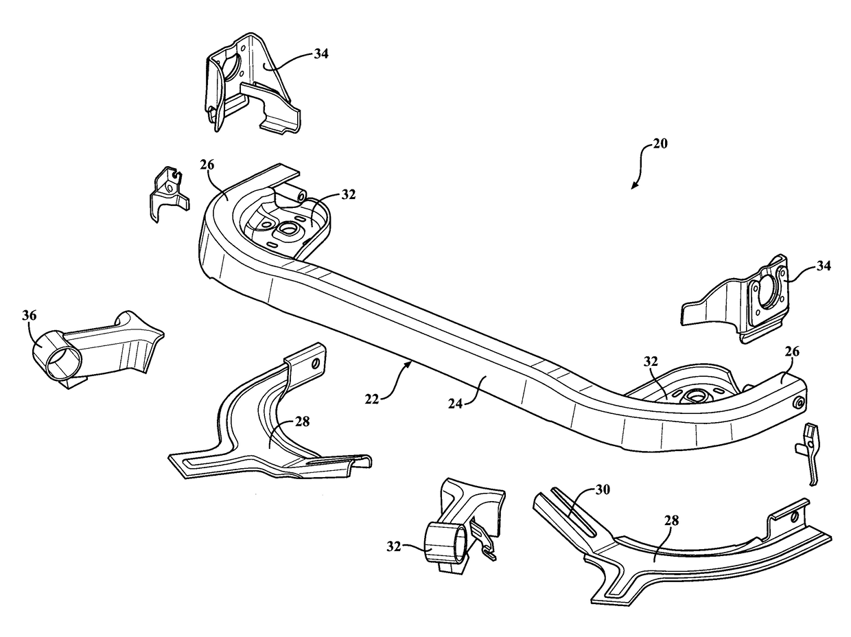
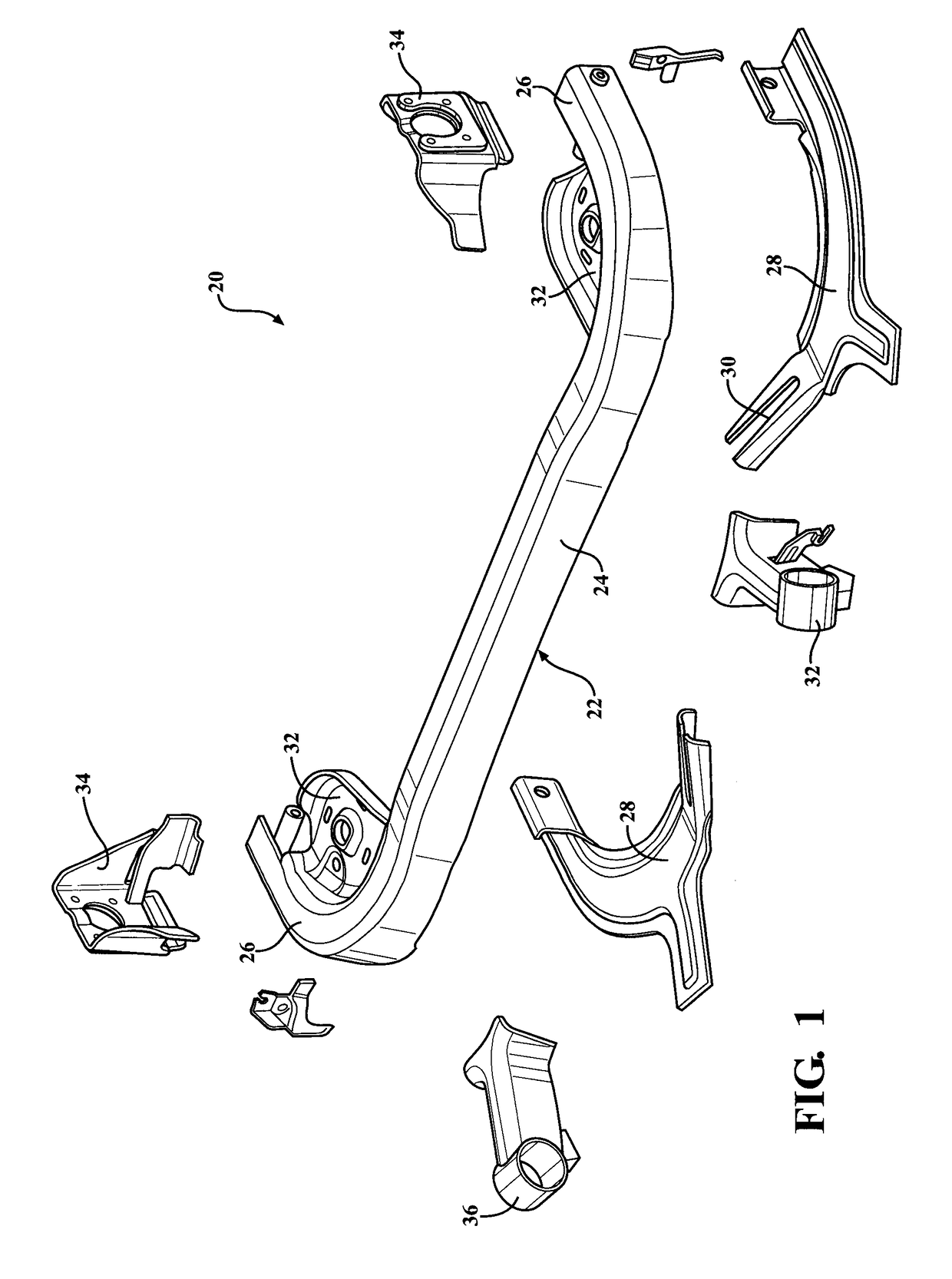
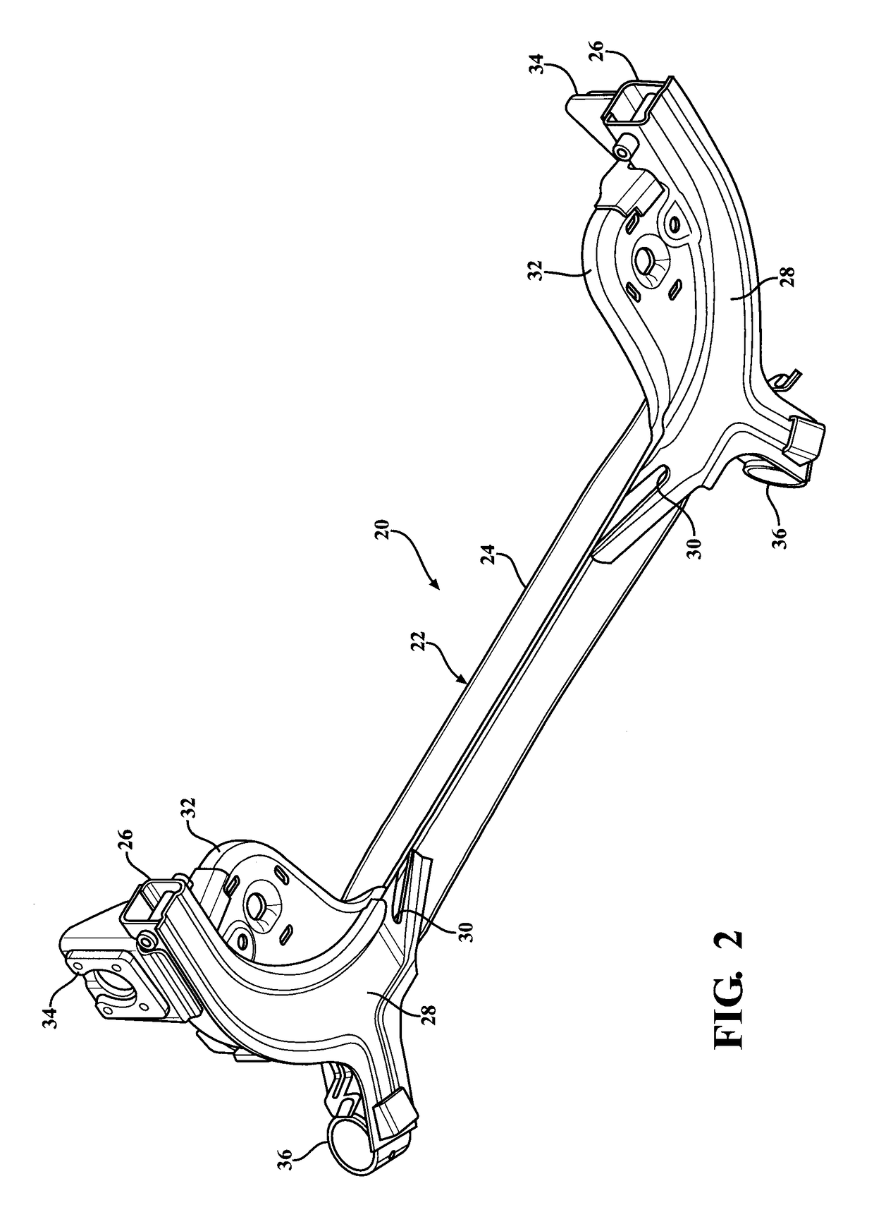
[0026]Referring to the Figures, wherein like numerals indicate corresponding parts throughout the several views, a first exemplary embodiment of an improved twist axle assembly 20 for suspension system of a vehicle is generally shown in FIGS. 1-7.

[0027]The twist axle assembly 20 includes a twist beam 22 (also known as a cross-member) which is generally U-shaped when viewed from above or below (see FIGS. 4 and 5) and extends between opposite ends. That is, the twist beam 22 has a middle section 24 which extends in a first direction and a pair of trailing arm sections 26 which at least partially in a second direction that is generally perpendicular or transverse to the first direction. Hereinafter, the first direction is referred to as a “lateral” direction and the second direction is referred to as a “longitudinal direction” to reflect the orientation of the twist beam 22 when it is installed in the vehicle. Each of the trailing arm sections 26 is curved from the lateral direction of...


PUM


Abstract

The twist axle assembly includes a twist beam which is made of a single integral piece, extends along a length between opposite ends and the twist beam has an open cross-sectional shape between the ends. The twist beam is stamped into a U-shape with a middle section that extends in a first direction between a pair of trailing arm sections. The trailing arm sections extend at least partially in a second direction that is generally transverse to the first direction to reduce twisting stresses within the trailing arm portions during operation of the twist axle assembly.

Description

CROSS REFERENCE TO RELATED APPLICATIONS[0001]This PCT Patent Application claims the benefit of and priority to U.S. Provisional Patent Application Ser. No. 62 / 086,816 filed Dec. 3, 2014, the entire disclosure of the application being considered part of the disclosure of this application, and hereby incorporated by reference.BACKGROUND OF THE INVENTION1. Field of the Invention[0002]The present invention is related, generally, to vehicle twist axle assemblies for use in vehicle suspension systems.2. Related Art[0003]A twist beam rear axle suspension assembly, also known as a torsion beam axle, is a type of automobile suspension system including a pair of trailing arms, each of which is coupled with a wheel of a vehicle and with an axle of the vehicle, and a twist beam which extends transversely between the trailing arms. During operation of the vehicle, the twist beam deforms in a twisting movement when one of the wheels moves relative to another, such as during vehicle body roll or w...

Claims


Application Information

Patent Timeline
Patent Type & Authority Applications(United States)
IPC IPC(8): B60G21/05B21D53/88
CPCB60G21/052B60G2206/20B60G2200/21B21D53/88B60G21/051B60G2200/20
Inventor HALBAUER, JOHANNES PETER
Owner MAGNA INTERNATIONAL INC
Why Eureka
Try Eureka