Anti-extrusion barrier for packing element

a technology of anti-extrusion and packing elements, which is applied in the direction of sealing/packing, earthwork drilling and mining, borehole/well accessories, etc., can solve the problems of leakage of sealing seals, no longer being able to maintain seals with seal bores,

Active Publication Date: 2017-12-07
WEATHERFORD TECH HLDG LLC
View PDF3 Cites 4 Cited by
  • Summary
  • Abstract
  • Description
  • Claims
  • Application Information

AI Technical Summary

Benefits of technology

The present disclosure provides an anti-extrusion device for use in packers and bridge plugs. The device includes a supporting member and a garter spring surrounding the supporting member, which prevents deformation of the device during use. The device can be extended or retracted without creating a gap in the inner volume of the garter spring, making it suitable for use in various applications such as packers and bridge plugs.

Problems solved by technology

If the extrusion is severe, the compression set element will no longer be able to maintain a seal with the seal bore.
However, when the packer or plug works at an environment of high pressure and / or high temperature, existing anti-extrusion devices are not adequate resulting in a leaky seal.

Method used


Image

  • Anti-extrusion barrier for packing element
  • Anti-extrusion barrier for packing element
  • Anti-extrusion barrier for packing element

Examples


Embodiment Construction

[0045]In the following description, numerous specific details are set forth to provide a more thorough understanding of the present disclosure. However, it will be apparent to one of skill in the art that the present disclosure may be practiced without one or more of these specific details. In other instances, well-known features have not been described in order to avoid obscuring the present disclosure.

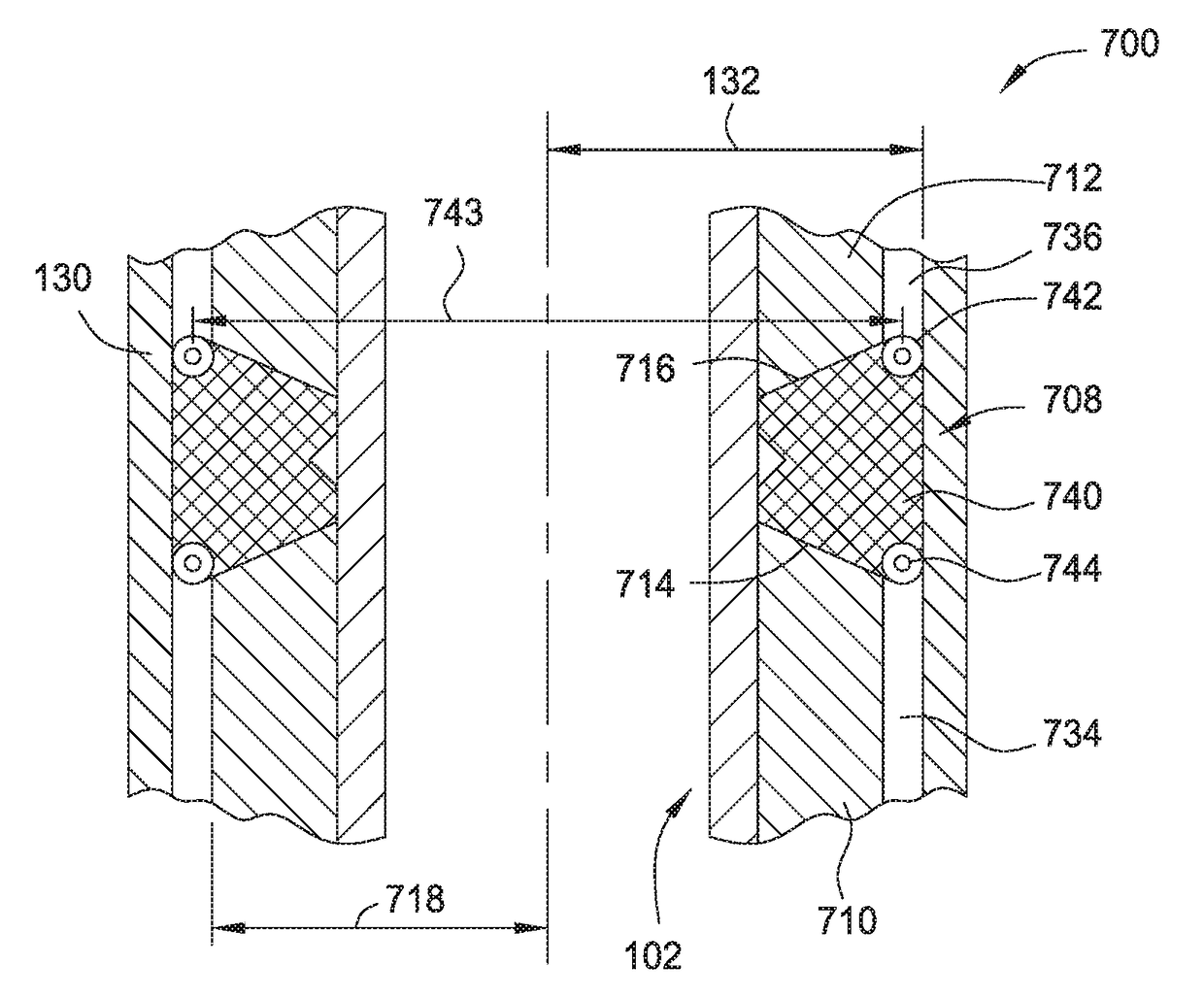
[0046]Embodiments of the present disclosure generally relate to an anti-extrusion device used in a packer or a bridge plug. The anti-extrusion device according to the present disclosure may include a garter spring and a solid support assembly substantially filled an inner volume of the garter spring. The support assembly may extend and retract with the garter spring while maintaining continuous support and / or barrier along the entire circumference of the garter spring. In one embodiment, the support assembly may include two C-rings having non-overlapping openings. In another embodime...


PUM


Abstract

Embodiments of the present disclosure generally relate to an anti-extrusion device used in a packer or a bridge plug. The anti-extrusion device includes a garter spring and a support assembly having a ring shaped body disposed in an entire circumference of an inner volume of the garter spring. The ring shaped body expands with expansion of the garter spring while maintaining a continuous ring.

Description

BACKGROUNDField[0001]Embodiments of the present disclosure relate to anti-extrusion barriers for packing element.Description of the Related Art[0002]During hydrocarbon recovery, operators may deploy packers and bridge plugs downhole to isolate portions of a borehole for various operations. Typically, the packer or bridge plug has a deformable element used to form a seal against the surrounding borehole wall. When being deployed, the deformable element may need to pass through a restriction that is smaller than the diameter of the borehole where the element is to be set. Once deployed at the desired location, the deformable element can then be set by compression, inflation, or swelling depending on the type of element used. For example, a compression set element in a packer or plug having a sleeve that is compressed to increase the element's diameter to form a seal. Extrusion may occur when a portion of the compression set element flows into a gap between the seal bore and the packer...

Claims


Application Information

Patent Timeline
IPC IPC(8): E21B33/128E21B33/134
CPCE21B33/134E21B33/128E21B33/1216
Inventor INGRAM, GARY DURONHARRALL, SIMON J.
Owner WEATHERFORD TECH HLDG LLC
Why Eureka
Try Eureka