
Connector for a compressor assembly

Active Publication Date: 2017-11-23
KONINKLJIJKE PHILIPS NV
View PDF3 Cites 2 Cited by
  • Summary
  • Abstract
  • Description
  • Claims
  • Application Information

AI Technical Summary

Benefits of technology

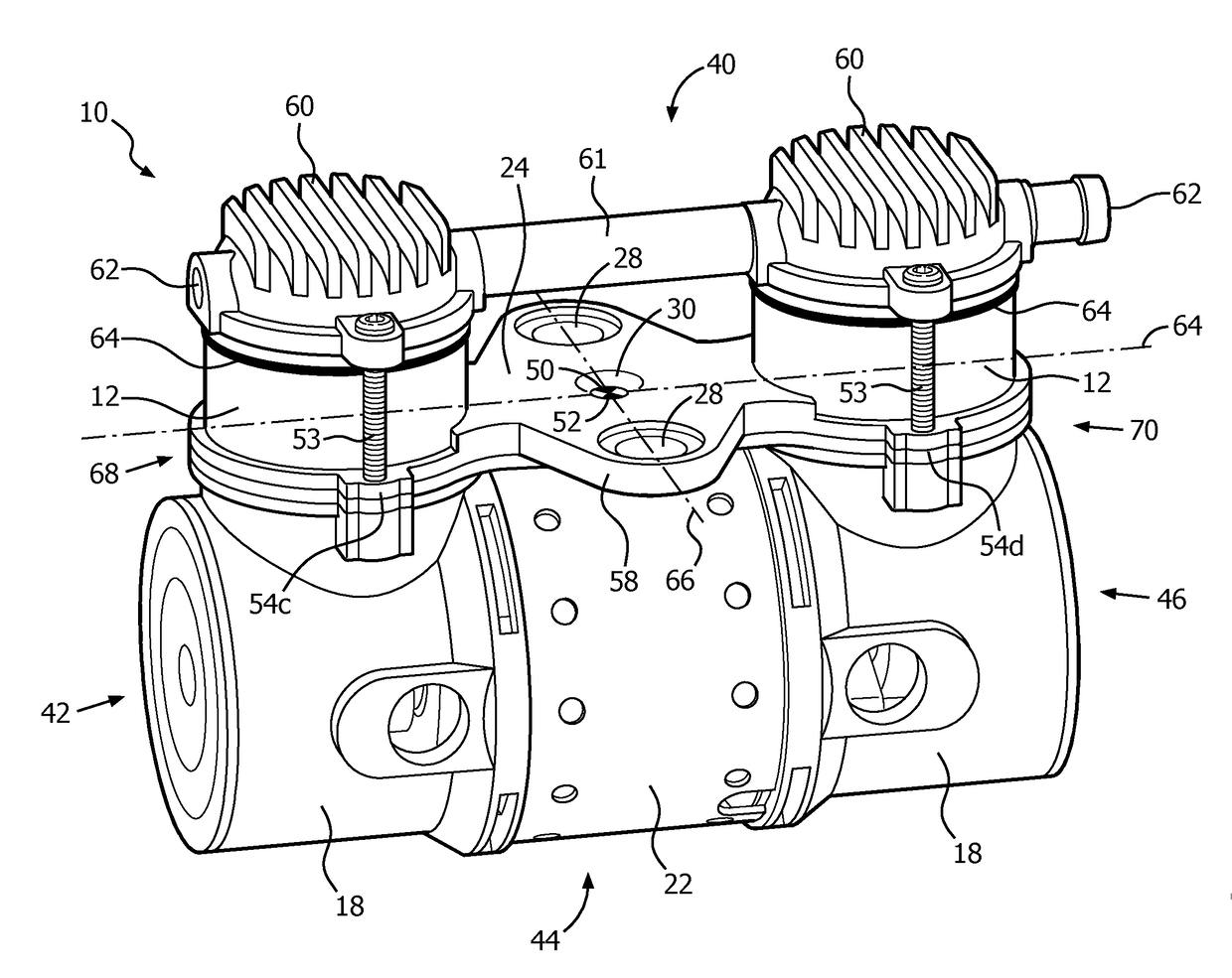
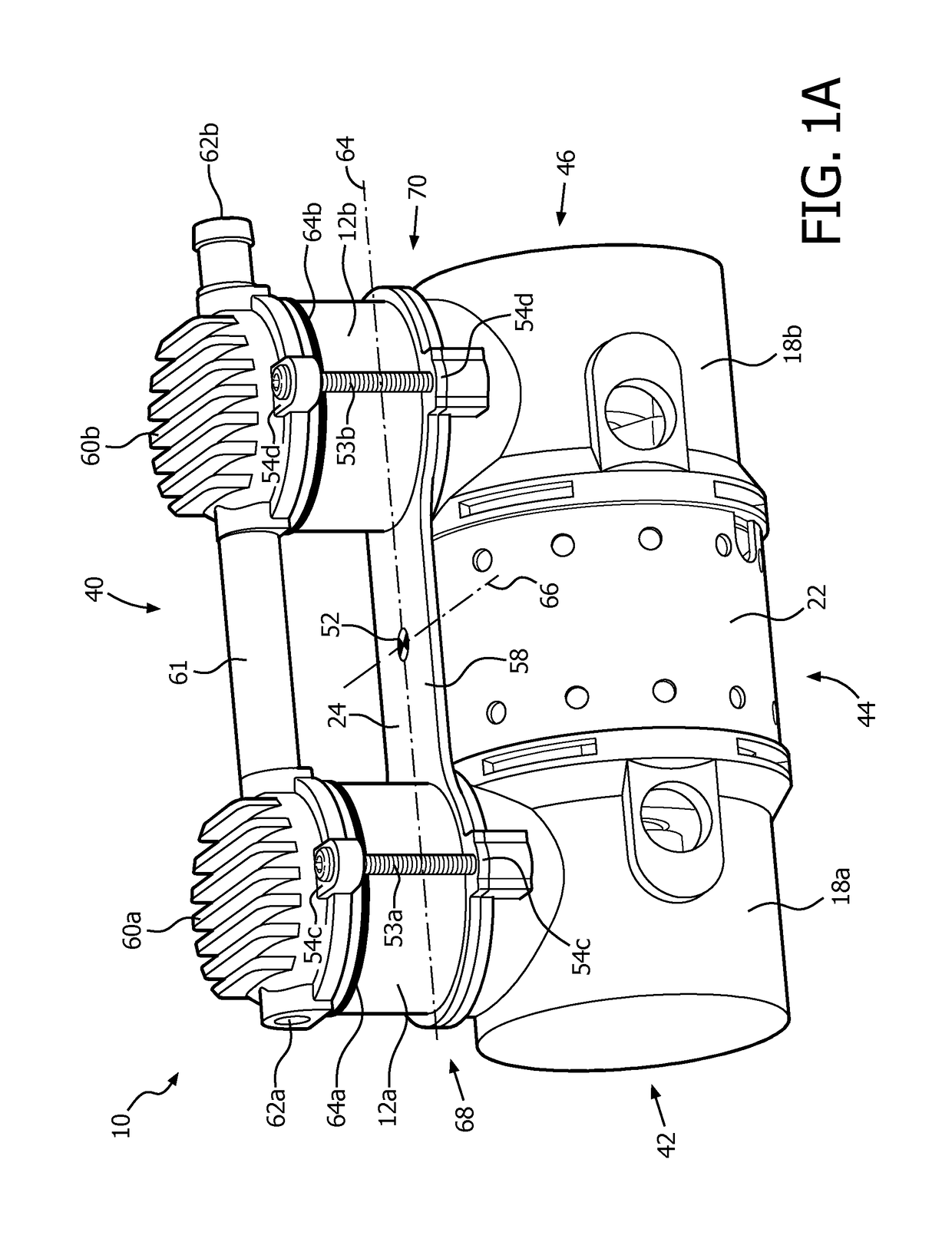
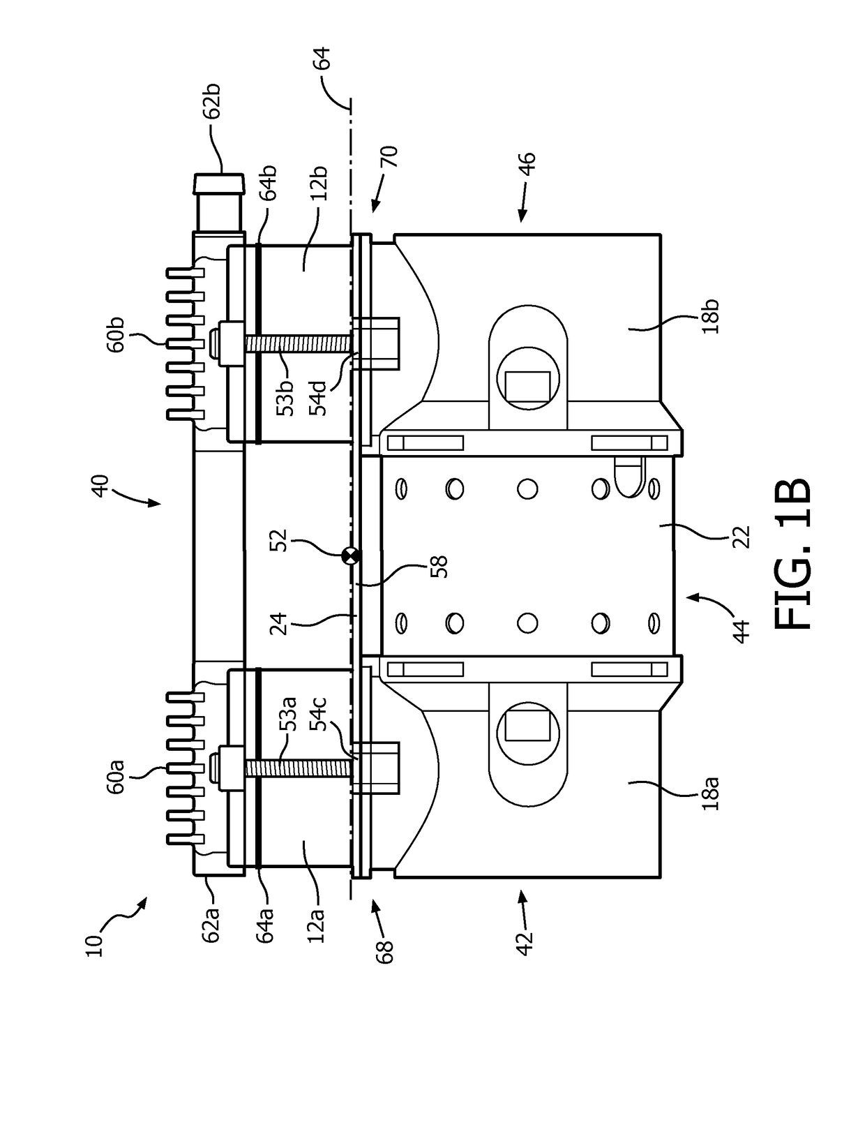
The present disclosure relates to a compressor assembly for increasing the pressure of a fluid. The assembly includes a first cylinder for compressing the fluid, a first piston, a first crank shaft, a second cylinder, a second piston, a second crank shaft, a motor housing, and a motor. The compressor assembly also includes a connector that connects the first and second cylinders, and a system for maintaining the operative couplings between the various components. The technical effect of the present disclosure is to provide a compressor assembly that can efficiently compress fluids to high pressures.

Problems solved by technology

The cup seal flexes during movement of the piston within the cylinder and the frictional engagement creates wear along the cup seal.
This heat hastens failure of the flexible cup seal, thus limiting the life of the compressor.
This is problematic when the thermal heat from the motor exceeds the heat being generated at or within the cylinder.
However, this may cause the device that includes such compressor and fan to be larger and bulkier.
However, this may cause the compressor to be bulkier, more expensive to manufacture, and inefficient.

Method used


Image

  • Connector for a compressor assembly
  • Connector for a compressor assembly
  • Connector for a compressor assembly

Examples


Embodiment Construction

[0021]As used herein, the singular form of “a”, “an”, and “the” include plural references unless the context clearly dictates otherwise. As used herein, the statement that two or more parts or components are “coupled” shall mean that the parts are joined or operate together either directly or indirectly, i.e., through one or more intermediate parts or components, so long as a link occurs. As used herein, “directly coupled” means that two elements are directly in contact with each other. As used herein, “fixedly coupled” or “fixed” means that two components are coupled so as to move as one while maintaining a constant orientation relative to each other.

[0022]As used herein, the word “unitary” means a component is created as a single piece or unit. That is, a component that includes pieces that are created separately and then coupled together as a unit is not a “unitary” component or body. As employed herein, the statement that two or more parts or components “engage” one another shal...


PUM


Abstract

A connector (24) and method of connecting a compressor assembly (10) that increases the pressure of a fluid are described. The compressor assembly (10) includes cylinders (12a,b), crank shaft housings (18a,b), and a motor housing (22). The connector (24) is disposed between the cylinders (12a,b) and the crank shaft housing (18a,b) and configured to engage the cylinders (12a,b) such that vibration during operation of the compressor assembly is reduced through the placement of the connector (24) corresponding to a center of gravity of the compressor assembly (10). The connector may also be used by the compressor assembly as a heat sink, inlet, mount, filter, and / or to provide other functions that improve the operation of compressor assembly.

Description

CROSS-REFERENCE TO RELATED APPLICATIONS[0001]This patent application claims the priority benefit under 35 U.S.C. §119(e) of U.S. Provisional Application No. 62 / 077,603, filed on Nov. 10, 2014, the contents of which are herein incorporated by reference.BACKGROUND OF THE INVENTION1. Field of the Invention[0002]The present disclosure pertains to a connector coupled with a compressor assembly.2. Description of the Related Art[0003]Typically, a compressor receives a supply of fluid, such as a liquid or gas, at a first pressure and increases the pressure of the fluid by forcing a given quantity of the received fluid having a first volume into a smaller second volume using a piston assembly. Some compressors have a reciprocating piston that reciprocates within the cylinder to compress the fluid. The pistons may be connected to a crank shaft housed in a crank shaft housing. The crank shaft may be operated by a motor housed in a motor housing. A typical piston assembly includes a cup seal to...

Claims


Application Information

Patent Timeline
IPC IPC(8): F04B27/00F04B39/16F04B39/06F04B35/01F04B39/00F04B53/00F04B39/12
CPCF04B27/005F04B35/01F04B39/0005F04B53/001F04B39/06F04B39/121F04B39/16F04B39/0094F04B35/06F04B41/06F04B39/125F04B39/123F04B35/04
Inventor VENTRAPRAGADA, VARAPRASAD
Owner KONINKLJIJKE PHILIPS NV
Learn More