
Method and apparatus for noninvasive inhibition of deep vein thrombosis

a deep vein thrombosis and non-invasive technology, applied in the field of electric stimulation of the foot muscles, can solve the problems of bringing on thrombosis, affecting cardiovascular circulation, and affecting the recovery of individuals, so as to reduce the pooling of blood, and enhance venous blood flow

Inactive Publication Date: 2017-11-23
STIMMED
View PDF2 Cites 14 Cited by
  • Summary
  • Abstract
  • Description
  • Claims
  • Application Information

AI Technical Summary

Benefits of technology

The system effectively prevents DVT, enhances venous blood flow, reduces neuropathic and musculoskeletal pain, and promotes wound healing by generating a tapping sensation through intermittent muscle stimulation, providing a portable and safer alternative for DVT prevention and pain management.

Problems solved by technology

The condition can be life-threatening if a blood clot migrates to the lung, resulting in pulmonary embolism (PE), or otherwise interferes with cardiovascular circulation.
More generally, venous thromboembolic disease (VTED) is a cause of significant morbidity and mortality for individuals immobilized after orthopedic surgery, due to neurologic disorders, even during prolonged travel, and a variety of other conditions.
Since 1954, it has been known that prolonged dependency stasis, a state imposed by airplane flights, automobiles trips and even attendance at the theater may bring on thrombosis.
Pneumatic compression equipment is often too cumbersome for mobile patients, or during prolonged travel.
Anticoagulation therapy carries the risk of bleeding complications and must be started several days in advance to be effective.

Method used


Image

  • Method and apparatus for noninvasive inhibition of deep vein thrombosis
  • Method and apparatus for noninvasive inhibition of deep vein thrombosis
  • Method and apparatus for noninvasive inhibition of deep vein thrombosis

Examples


Embodiment Construction

[0090]Aspects of the present invention provide an improved system, device, and method of administering electrical stimulation to the muscles of the foot.

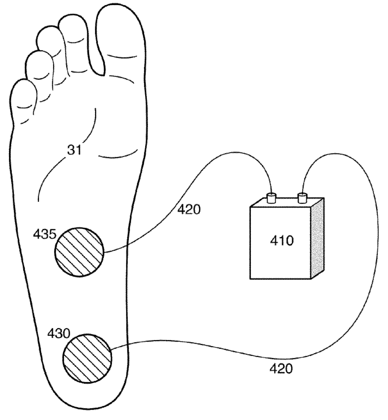
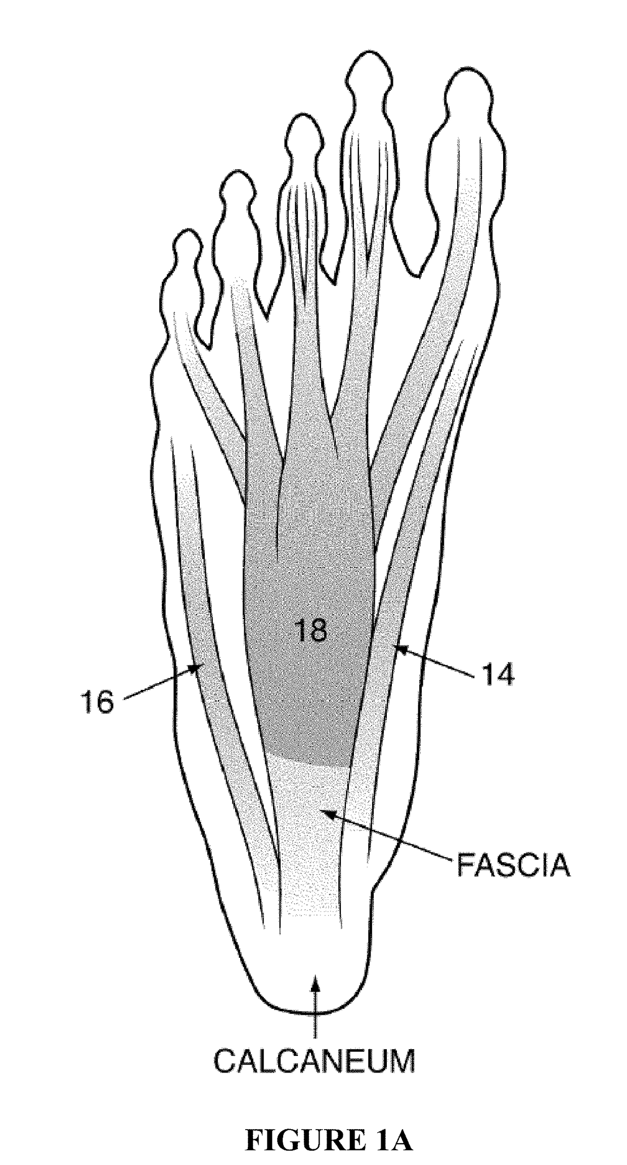
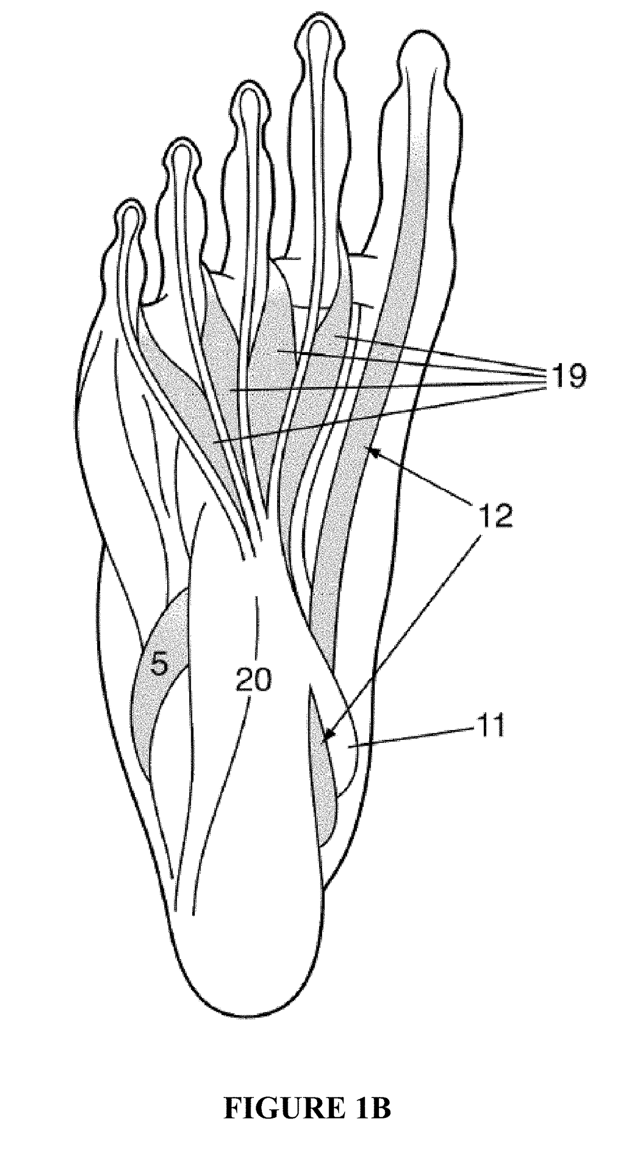
[0091]Aspects of the present invention provide a programmable electrical pulse generator for delivering an electrical current of mild and tolerable intensity to the muscles of the foot, which results in a mild contraction of the muscles. In various aspects of the present invention, the contraction may be accomplished by placing surface electrodes on the soles of the feet or at the ankles. When placed on the soles, the active surface electrodes are placed over the larger muscles of the first layer that are closer to the surface of the skin and in an area where callousing of the skin and the fat layer is minimal such as the mid-foot and arch area. The ground electrodes may be placed over or proximal to the heel. By stimulating the foot muscles in this manner, blood pooling in the calf veins is prevented. When placed on the side or top...


PUM


Abstract

System, device and method for providing neuromuscular electrical stimulation (NMES) to muscles of foot. The device includes an electrical signal generator for producing a wave pattern of variable frequency, duration, intensity, ramp time and on-off cycle. The device further includes surface electrodes for being positioned over the foot muscles or around ankles and attached to the signal generator. The device includes a wearable device for positioning a first electrode adjacent a heel of the wearer's foot and a second electrode adjacent an arch of the foot. The signal generator is programmed to stimulate the foot muscles and nerves. Location of the electrodes and the programming are adjusted to reduce pooling of the blood in the soleal veins of the calf and enhance venous blood flow to prevent deep vein thrombosis (DVT); to enhance venous blood flow for the post-thrombotic syndrome patient; to expedite wound healing; to reduce neuropathic pain of the foot and ankle, chronic musculoskeletal pain of the ankle and foot, and acute post-operative foot and ankle pain; and to prevent muscular atrophy of the foot muscles.

Description

INCORPORATION BY REFERENCE TO ANY PRIORITY APPLICATIONS[0001]This application is a continuation application of U.S. patent application Ser. No. 15 / 287,531, filed on Oct. 6, 2016, which a continuation-in-part application of U.S. patent application Ser. No. 15 / 204,625, filed on Jul. 7, 2016, which is a continuation of U.S. patent application Ser. No. 12 / 687,935, filed on Jan. 15, 2010, all of which are hereby incorporated by reference in their entirety.BACKGROUND OF THE INVENTIONField of the Invention[0002]The present invention pertains generally to the field of the electrical stimulation of muscles for prevention of thrombosis and for pain management and, more particularly, to electrical stimulation of muscles of the foot.Description of the Related Art[0003]Electrical stimulation of muscles and nerves by applying electrodes over the skin is currently used for enhancing blood circulation and reducing blood clots and for scrambling the pain signal that reach the brain in order to manag...

Claims


Application Information

Patent Timeline
Patent Type & Authority Applications(United States)
IPC IPC(8): A61N1/04A61N1/36
CPCA61N1/0452A61N1/36021A61N1/36003A61N1/0456
Inventor KAPLAN, ROBERT EDWARDCZYMY, JAMES JOSEPHFRIEDMAN, SCOTT E.
Owner STIMMED
Learn More