


Quick Research
Generate reliable direction feasibility study reports for your R&D in just a few steps.

Technical Q&A
Discover and master advanced knowledge NOW. Basics, ideas, possibilities, all at once.

Find Solutions
As an expert in R&D theories, this can generate solutions to your technical problems instantly.

Evaluate Feasibility
Analyze your overall solution with one click, know your potential R&D risks in advance.

Monitor Landscape
Get weekly tech updates, stay abreast of the latest tech innovations and key insights.
Three-dimensional thermal imaging for medical applications
a three-dimensional thermal imaging and medical application technology, applied in the field of thermal imaging, can solve the problems of unaddressed need in the industry, and achieve the effect of improving diagnostic accuracy and accuracy
- Summary
- Abstract
- Description
- Claims
- Application Information
AI Technical Summary
Benefits of technology
Problems solved by technology
Method used
Image

Examples
Embodiment Construction
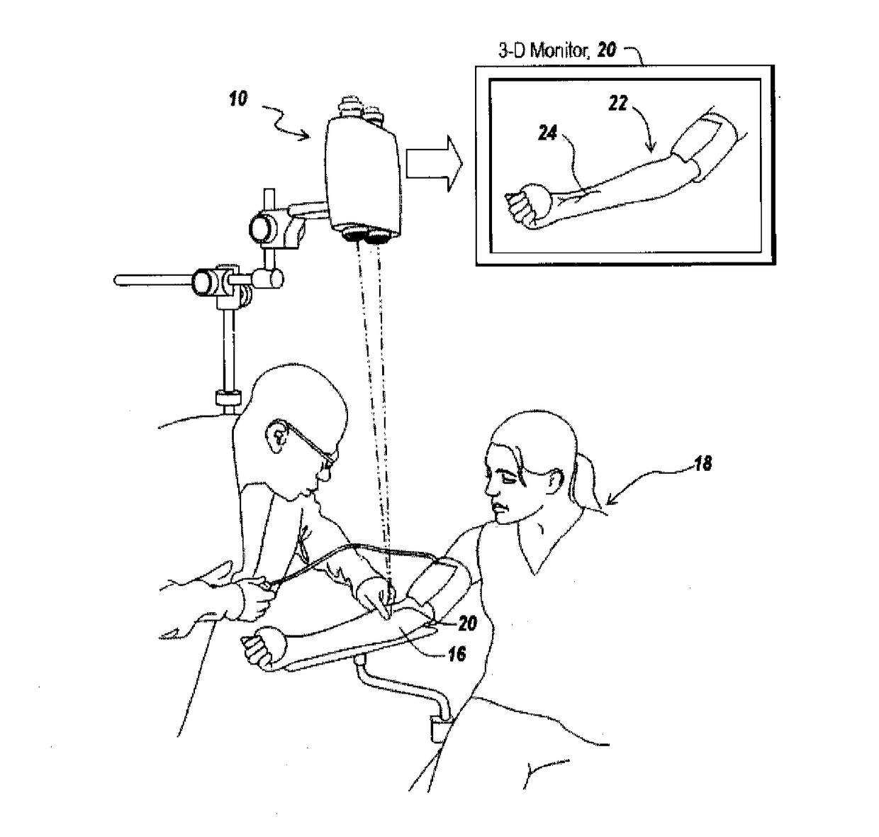
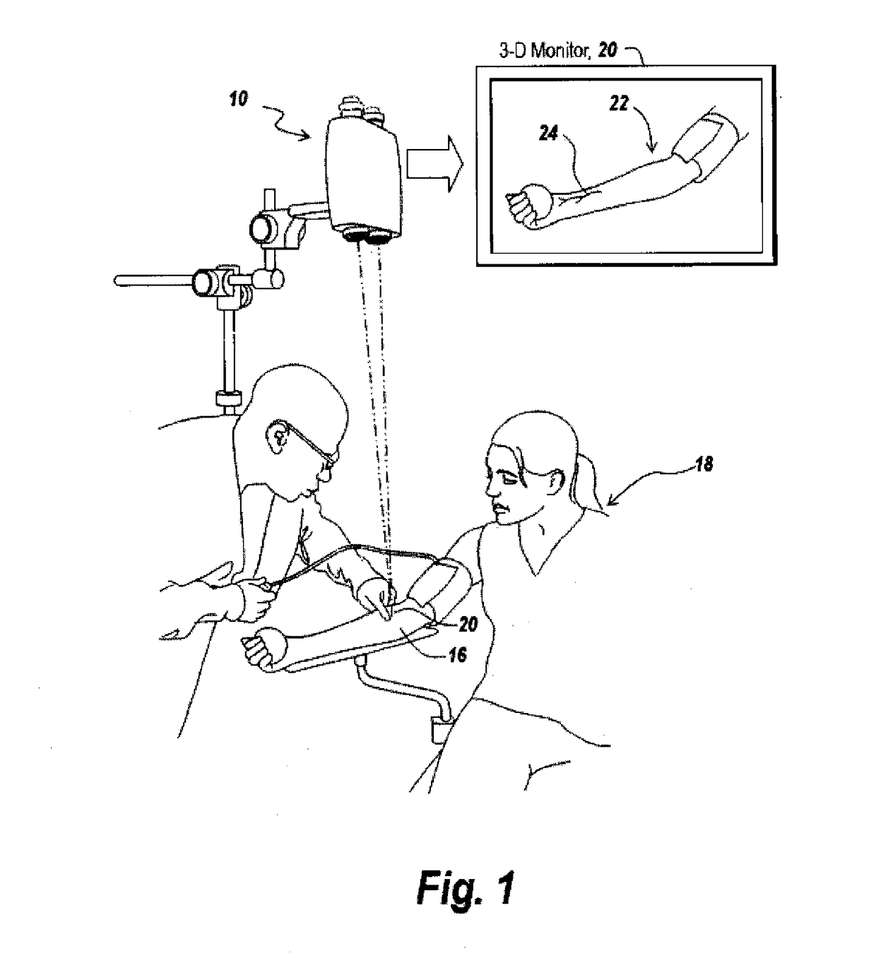
[0017]FIG. 1 is a perspective drawing showing a preferred embodiment of a dual channel imager system of the invention with an example user setting. Specifically, FIG. 1 is an example diagrammatic illustration of the utilization of the subject binocular infrared system for identifying blood vessels in the arm of a patient undergoing a phlebotomy. The presented invention is envisioned to have utility in identifying blood vessels in the arm of a patient and other medical procedures where depth perception is important as a diagnostic aid.
[0018]In the illustrated system, subsurface anatomical features, for instance, in the arm 16 of a patient 18 are detected through a binocular infrared camera system 10 which is focused on the subsurface region of the patient's arm as illustrated at 16. Here, the output of camera 10, is coupled to a 3-D monitor 20 which produces a three-dimensional image 22 of the patient's arm, and more particularly, a subsurface vein, such as vein 24 which is shown in ...
PUM
 Abstract
Description
Claims
Application Information
 - R&D Engineer
- R&D Manager
- IP Professional
- Industry Leading Data Capabilities
- Powerful AI technology
- Patent DNA Extraction
Browse by: Latest US Patents, China's latest patents, Technical Efficacy Thesaurus, Application Domain, Technology Topic, Popular Technical Reports.
© 2024 PatSnap. All rights reserved.Legal|Privacy policy|Modern Slavery Act Transparency Statement|Sitemap|About US| Contact US: help@patsnap.com