Suspension systems, wheel spindle assemblies, and methods of retrofitting wheel spindles

a technology of suspension system and wheel spindle, which is applied in the direction of suspension system, suspension arm, and suspension component. it can solve the problems that the newer vehicle suspension system continues to pose additional challenges in the modification of the suspension system

Active Publication Date: 2017-10-26
VANTAGE MOBILITY INT
View PDF0 Cites 8 Cited by
  • Summary
  • Abstract
  • Description
  • Claims
  • Application Information

AI Technical Summary

Benefits of technology

[0007]An A-arm suspension system according to one embodiment of the present invention may include a frame that defines respective left and right rear body mounting locations at about a rear end of the frame and respective left and right front body mounting locations at about a front end of the frame. A right side control arm is pivotally mounted to a right side of said frame so that at least a portion of the right side control arm is generally aligned with the right front body mounting location on the frame. A right side A-arm is pivotally mounted to the right side of the frame assembly in generally spaced-apart relation to the right side control arm so that the right side control arm an

Problems solved by technology

In addition, it is often necessary to modify the vehicle suspension systems to provide the additional space or clearance required by the deployable ramp systems.
While a wide variety of suspension system

Method used


Image

  • Suspension systems, wheel spindle assemblies, and methods of retrofitting wheel spindles
  • Suspension systems, wheel spindle assemblies, and methods of retrofitting wheel spindles
  • Suspension systems, wheel spindle assemblies, and methods of retrofitting wheel spindles

Examples


Embodiment Construction

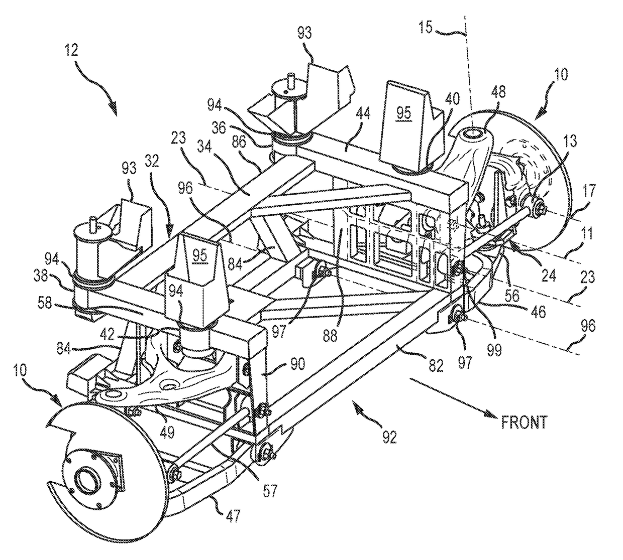
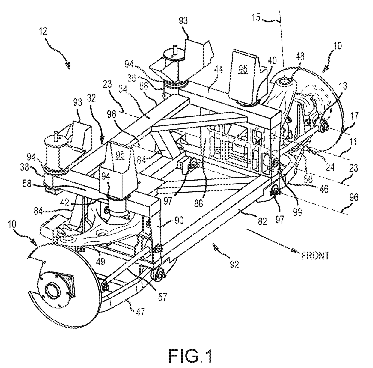
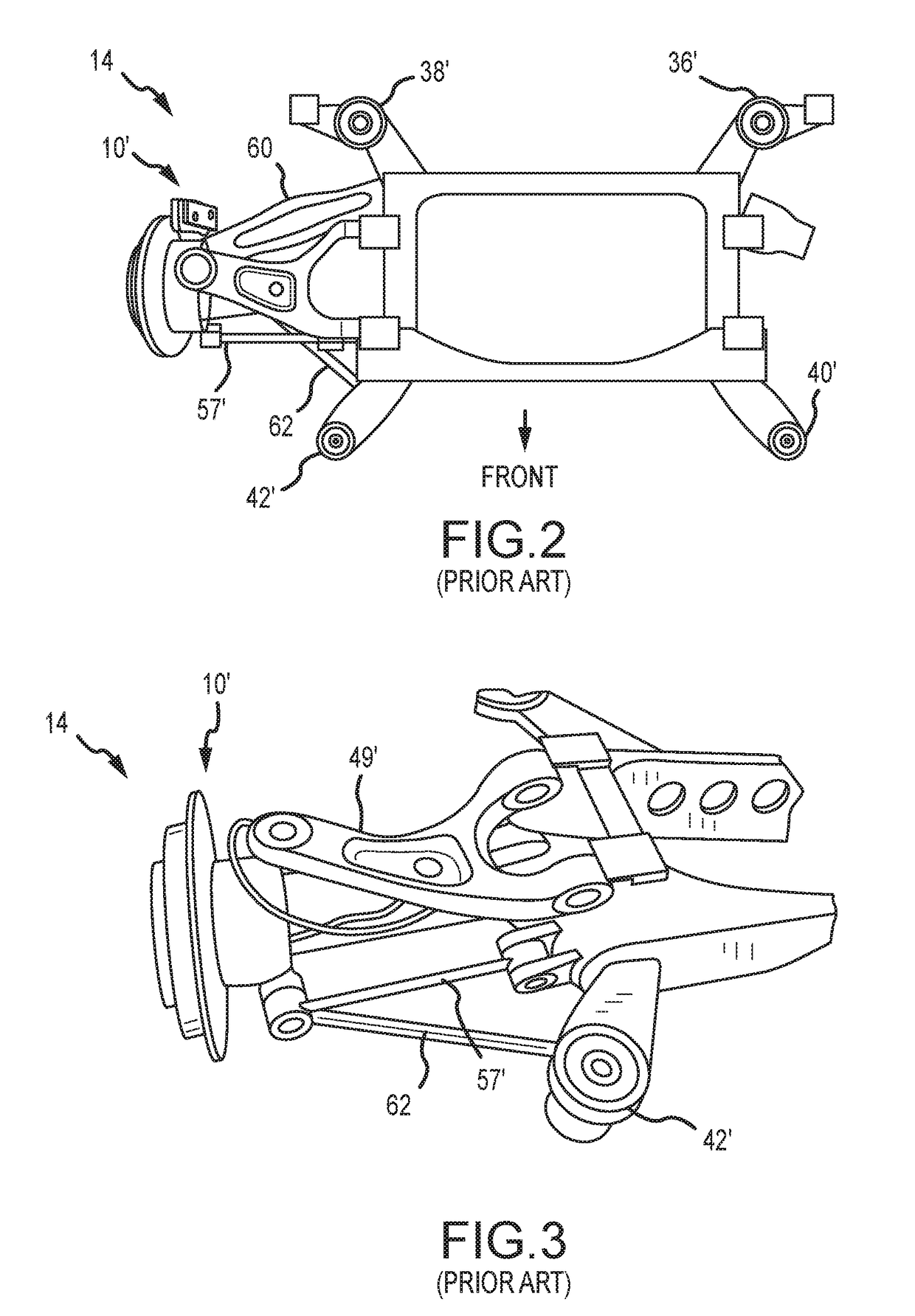
[0020]A wheel spindle assembly 10 according to one embodiment of the present invention is shown and described herein as it could be used in conjunction with an A-arm suspension system 12, as best seen in FIG. 1. The A-arm suspension system 12 may be used to replace a multi-link original equipment manufacturer (OEM) suspension system 14, an example of which is illustrated in FIGS. 2 and 3. Such a replacement or substitution will allow a vehicle (not shown) designed to receive the multi-link OEM suspension system 14 to be more easily converted for wheelchair use. In addition, the replacement of the OEM suspension system 14 with the A-arm suspension system 12 will also allow the modified vehicle to have increased interior space and flat floor area, as best seen in FIG. 11. Alternatively, other applications are possible.

[0021]Because the A-arm suspension system 12 of FIG. 1 may be used to replace the multi-link OEM suspension system 14 of FIGS. 2 and 3, it will be generally preferred, b...


PUM


Abstract

A method of mounting to an A-arm suspension system a wheel spindle configured for use with a multi-link suspension system may involve the steps of: Removing at least one suspension link mount on the wheel spindle; mounting a ball joint bracket to the wheel spindle, the ball joint bracket being configured to mount to the A-arm suspension system, the removing and mounting steps producing a modified wheel spindle; and mounting the modified wheel spindle to the A-arm suspension system.

Description

CROSS-REFERENCE TO RELATED APPLICATIONS[0001]This application claims the benefit of U.S. Provisional Patent Application Nos. 62 / 326,516, filed on Apr. 22, 2016, and 62 / 376,656, filed on Aug. 18, 2016, both of which are hereby incorporated herein by reference for all that they disclose.TECHNICAL FIELD[0002]The present invention relates to vehicle suspension systems in general and more specifically to modified vehicle suspension systems of the type commonly used in converting vehicles for wheelchair use.BACKGROUND[0003]Systems for converting vehicles for wheelchair use are well-known in the art and usually involve a wide range of additions and modifications to allow persons with limited mobility to more easily gain access to and / or operate such converted vehicles. For example, such vehicles are typically modified to include deployable ramp systems to allow persons in wheeled assistance devices, such as wheelchairs, scooters, and the like to enter the vehicles, either to operate the ve...

Claims


Application Information

Patent Timeline
IPC IPC(8): B60G3/20B60G7/00B62D65/12
CPCB60G3/20B62D65/12B60G7/001B60G7/005B60G2200/464B60G2204/143B60G2200/18B60G2200/4622B60G7/008
Inventor SCHMIDT, MICHAEL J.
Owner VANTAGE MOBILITY INT
Why Eureka
Try Eureka