
Magnetic component

a technology of magnetic components and components, applied in the direction of transformers/inductances magnetic cores, basic electric elements, electrical equipment, etc., can solve the problems of limiting potential design for volume reduction, bobbins b>12/b> adding to the material cost of transformers, etc., to improve the efficiency of magnetic components, increase the winding space of magnetic components, and reduce material costs

Active Publication Date: 2017-09-28
DELTA ELECTRONICS INC
View PDF6 Cites 5 Cited by
  • Summary
  • Abstract
  • Description
  • Claims
  • Application Information

AI Technical Summary

Benefits of technology

The patent text describes a new type of magnetic component that has no need for a bobbin, which is a common part of traditional magnetic components. The new design increases the space where the winding coils can be placed, improves efficiency, reduces material costs, reduces the size of the component and makes it easier to assemble.

Problems solved by technology

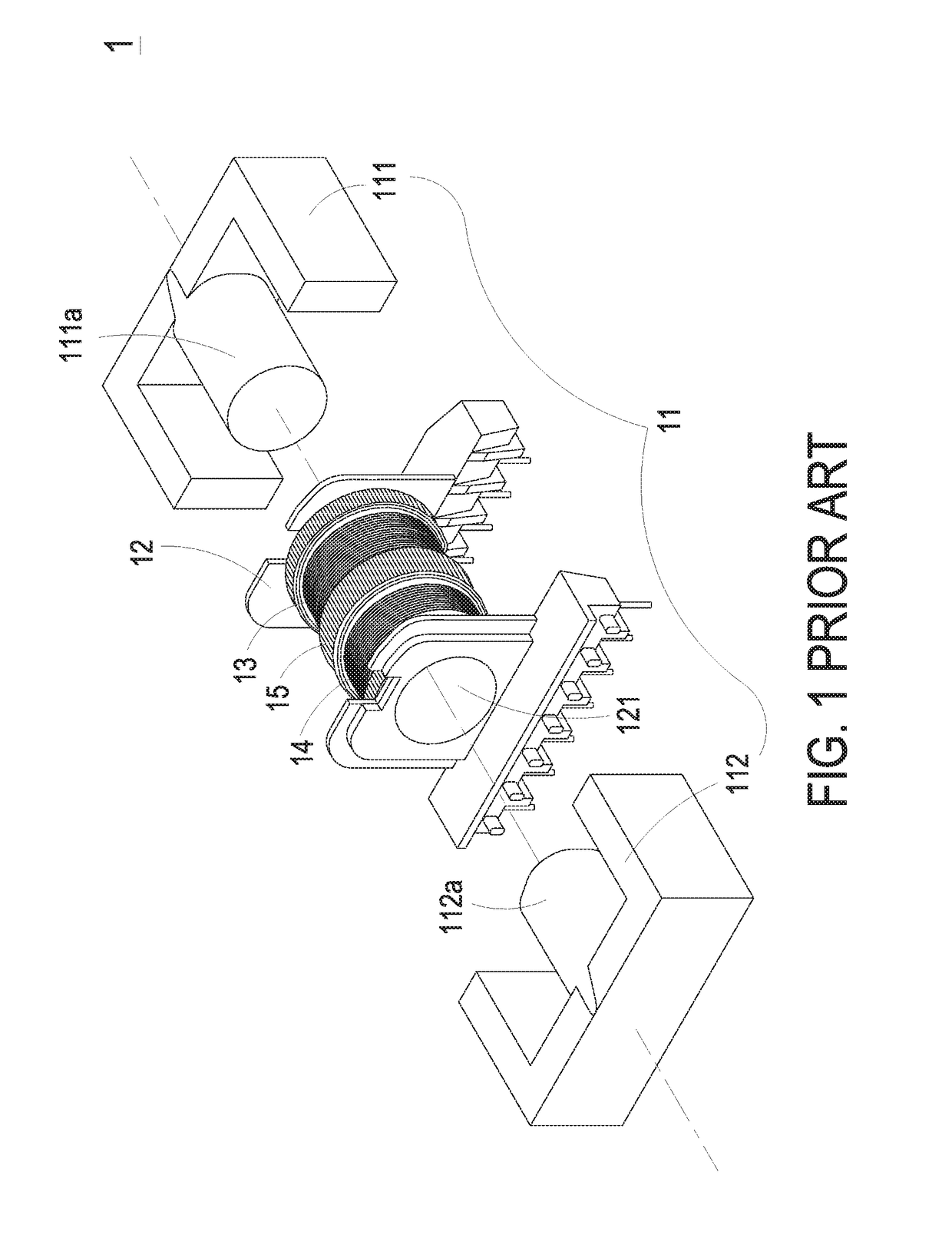
In addition, the bobbin 12 adds to the material cost of the transformer 1, as well as limiting potential designs for volume reduction.

Method used


Image

  • Magnetic component
  • Magnetic component
  • Magnetic component

Examples


Embodiment Construction

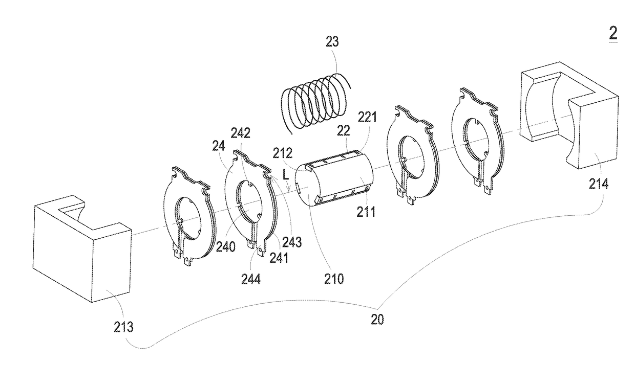
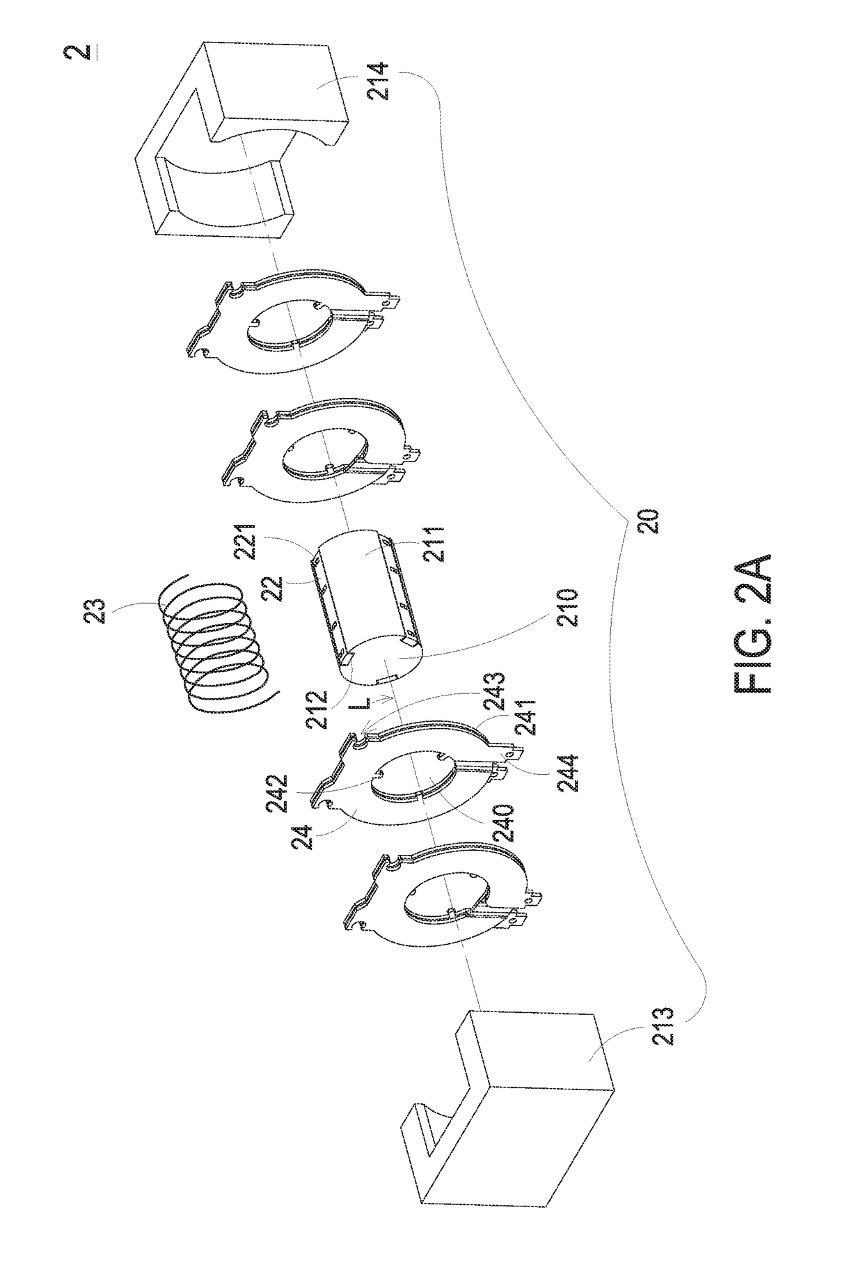
[0028]Referring to FIGS. 2A and 2B, a magnetic component 2 is provided, which can be, but not limited to, a transformer, an inductor or a filter. The magnetic component 2 includes a magnetic core assembly 20, at least a fastening set 22, a first winding set 23 and a plurality of second winding sets 24. The magnetic core assembly 20 includes at least a pillar 210 having an outer peripheral surface 211. The fastening set 22 is provided on the outer peripheral surface 211 of the pillar 210. The second winding sets 24 are spaced apart and sleeved around the outer peripheral surface 211 of the pillar 210. The second winding sets 24 may be affixed or attached on the pillar 210 via the fastening set 22 and configured to define at least a space for a winding zone A on the magnetic component 2. Namely, each two adjacent second winding sets 24 are configured to form the winding zone A. The first winding set 23 is insulated from the second winding sets 24, disposed around the outer peripheral ...


PUM

PropertyMeasurementUnit
magneticaaaaaaaaaa
conductiveaaaaaaaaaa
voltagesaaaaaaaaaa

Abstract

A magnetic component is disclosed. The magnetic component includes a magnetic core assembly, a fastening element, a first winding set and a second winding set. The magnetic core assembly includes at least a pillar. The fastening element is provided on an outer peripheral surface of the pillar. The first winding set is disposed around the outer peripheral surface of the pillar. The second winding set is disposed around the outer peripheral surface of the pillar and engaged with the fastening set. The first winding set and the second winding set are located adjacent to each other and disposed around the outer peripheral surface of the pillar.

Description

TECHNICAL FIELD[0001]The present disclosure relates to a magnetic component, and more particularly to a bobbinless magnetic component.BACKGROUND OF THE DISCLOSURE[0002]Transformers are magnetic assemblies and are widely applied in various electronic devices for regulating various voltages required for various kinds of electric appliances. With development trends of electronic devices such as power supplies toward more compact, high-power-density and high efficiency, it is desirable for transformers to have a compact design and high efficiency, so as to meet practical requirements.[0003]FIG. 1 is a schematic exploded view illustrating a conventional transformer 1, comprising a magnetic core assembly 11, a bobbin 12, a primary winding coil 13, a secondary winding coil 14 and an insulating tape 15. The primary winding coil 13 and the secondary winding coil 14 are wound around the bobbin 12 and separated from each other via the insulating tape 15. The magnetic core assembly 11 comprises...

Claims


Application Information

Patent Timeline
Patent Type & Authority Applications(United States)
IPC IPC(8): H01F27/29H01F27/24H01F27/28
CPCH01F27/29H01F27/24H01F27/2823H01F27/2847H01F3/10H01F27/28H01F27/2866H01F27/30H01F27/306
Inventor CHEN, YI-LINWU, YI-FANZHANG, ZHI-LIANGTENG, CHING-HSIENHUNG, YU-LIANGLIN, HAN-HSING
Owner DELTA ELECTRONICS INC
Learn More