
System for acquiring channel knowledge and method thereof

a channel knowledge and knowledge acquisition technology, applied in the field of channel knowledge acquisition system and a method, can solve the problems of difficult to obtain sufficient channel subspace samples within a practical coherence time, the exhaustive search method needs to sweep an extremely large number, and the limitation of channel knowledge acquisition, so as to reduce training overhead

Active Publication Date: 2017-09-21
MEDIATEK INC +1
View PDF1 Cites 3 Cited by
  • Summary
  • Abstract
  • Description
  • Claims
  • Application Information

AI Technical Summary

Benefits of technology

The invention helps reduce training costs by using specific technical solutions.

Problems solved by technology

However, the acquisition of channel knowledge suffers from a subspace sampling limitation in the hybrid beamforming structure, where antenna array is driven by only a limited number of radio frequency chains (RF-chains) to avoid the fabrication cost and energy consumption from massive number of high-frequency mixed-signal components.
However, the exhaustive search method needs to sweep an extremely high number of directional beams especially for beamforming systems with massive antennas.
Hence, it is difficult to obtain sufficient channel subspace samples within a practical coherence time to compute a meaningful estimate.
Moreover, the training overhead is significant.
Compared with the exhaustive search method, the required training overhead in hierarchical search method increases with the number of antennas in log manner rather than linear manner.
It may be challenging due to the complicated control plane and the unreliable transmission / reception without sufficient beamforming gains before beam training is completed.
Thus, the training overhead of the hierarchical search method may grow linearly with the increasing number of user equipment.
In summary, it can be seen that the prior art has encountered several issues of high training overhead for a long time.

Method used


Image

  • System for acquiring channel knowledge and method thereof
  • System for acquiring channel knowledge and method thereof
  • System for acquiring channel knowledge and method thereof

Examples


Embodiment Construction

[0022]The following describes implementation manners of the present invention with reference to the accompanying drawings and embodiments, so that an implementation process in the present invention of how to apply the technical solutions to resolve a technical problem and achieve a technical effect can be fully understood and implemented.

[0023]Before a system for acquiring channel knowledge and a method thereof disclosed in the present invention are described, the present invention is briefly described first. In the present invention, we aim to reduce the training overhead in beamforming systems. Owing to the reduced diffraction and the substantial losses incurred at each reflection in high-frequency bands, propagation paths of physicals channel tend to be sparse as the number of antennas increases in beamforming systems. Via exploiting sparse nature of physical channels in high-frequency bands, we can utilize some advanced algorithms like compressive sensing to reduce the training ...


PUM


Abstract

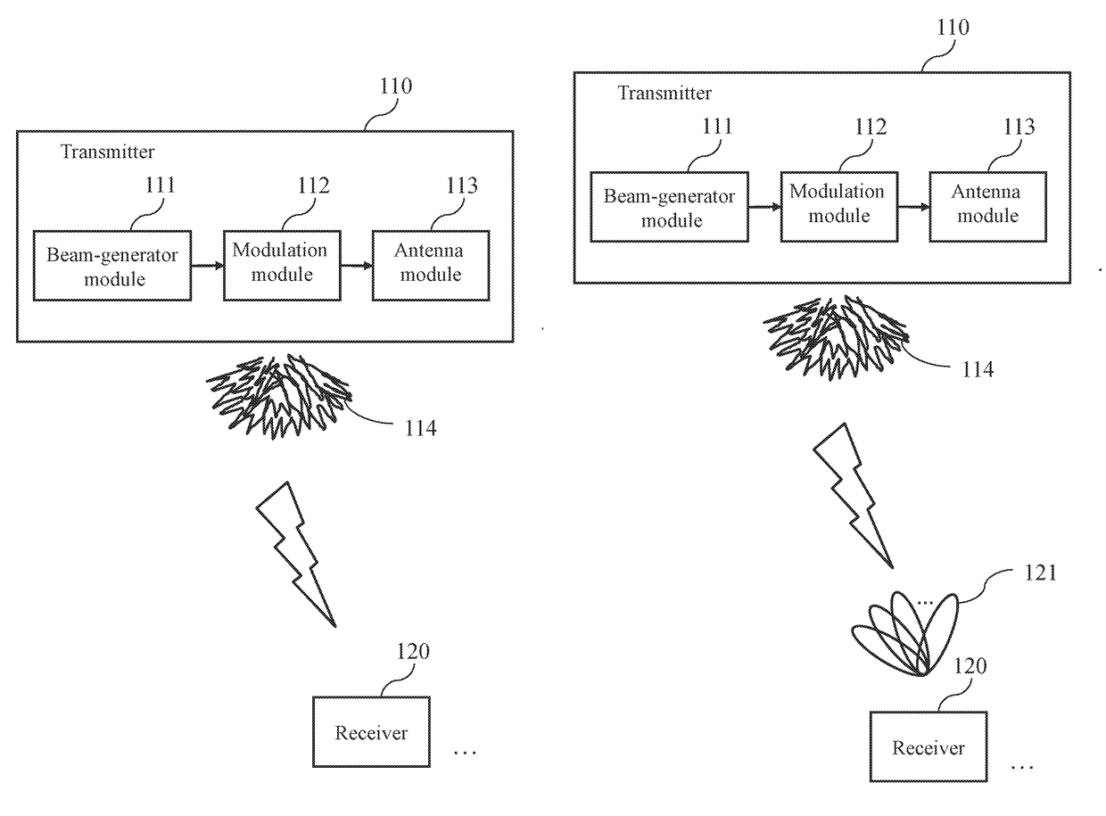
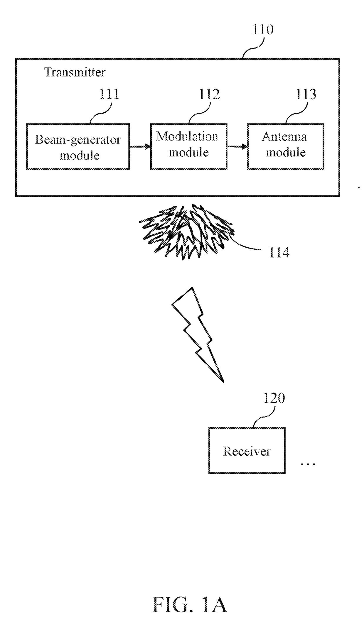
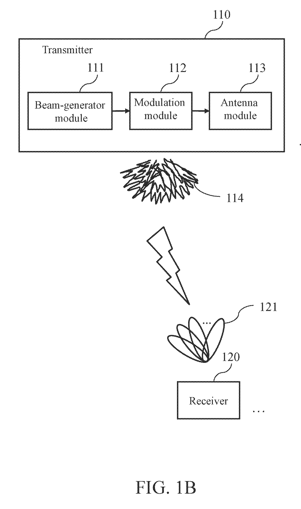
A system for acquiring channel knowledge and a method thereof are provided. At least one transmitter generates multiple directional beams in different directions, next modulates the directional beams in the different directions by means of at least one spreading sequence, so as to enlarge the beam range of each directional beam in the different directions and use the modulated directional beams as training-specific beams in the different directions, and sweeps the training-specific beams in the different directions by means of a plurality of antennas, so that at least one receiver measures at least one training-specific beam, and determines the channel knowledge according to the measurement result and beam-related information associated with the at least one training-specific beam, so as to achieve a technical effect of reducing training overhead.

Description

CROSS-REFERENCE TO RELATED APPLICATIONS[0001]The present application is based on, and claims priority from, U.S. Provisional Application Ser. No. 62 / 308,228, filed Mar. 15, 2016, the disclosure of which is hereby incorporated by reference herein in its entirety.BACKGROUND[0002]1. Technical Field[0003]The present invention relates to a channel knowledge acquisition system and a method thereof, and more particularly to a system for acquiring channel knowledge with low training overhead by exploiting sparse nature of physical channel and a method thereof.[0004]2. Description of Related Arts[0005]Typically, in order to adopt beamforming techniques to compensate for high expected pathloss of signals in high-frequency bands, the channel knowledge is necessary at both a transmitter (or referred to as a base station) and a receiver (or referred to as an user equipment), wherein the channel knowledge usually includes angles-of-departure and angles-of-arrival of dominant propagation paths. In...

Claims


Application Information

Patent Timeline
IPC IPC(8): H04B7/0408H04L25/03H04B7/06
CPCH04B7/0408H04L25/03961H04B7/0684H04B7/0617H04B7/0695H04B7/088H04L25/03898H04L25/0204
Inventor TSAI, CHENG-RUNGWU, AN-YEUCHEN, JU-YAZHOU, QIANG
Owner MEDIATEK INC
Learn More