Zip Line Brake
a technology of brakes and lines, applied in the direction of brakes for specific applications, railway braking systems, amusements, etc., can solve the problem of no solution for portable devices or methods, and achieve the effect of reducing spa
- Summary
- Abstract
- Description
- Claims
- Application Information
AI Technical Summary
Benefits of technology
Problems solved by technology
Method used
Image


Examples
Embodiment Construction
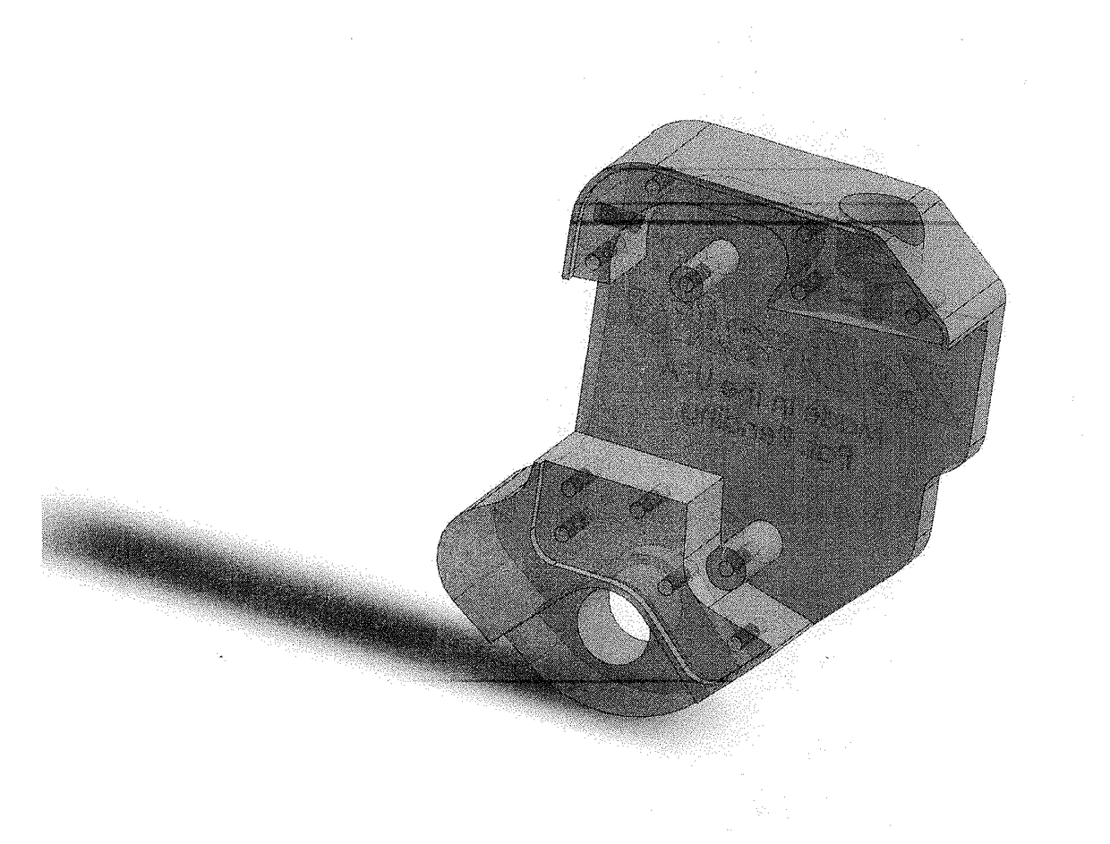
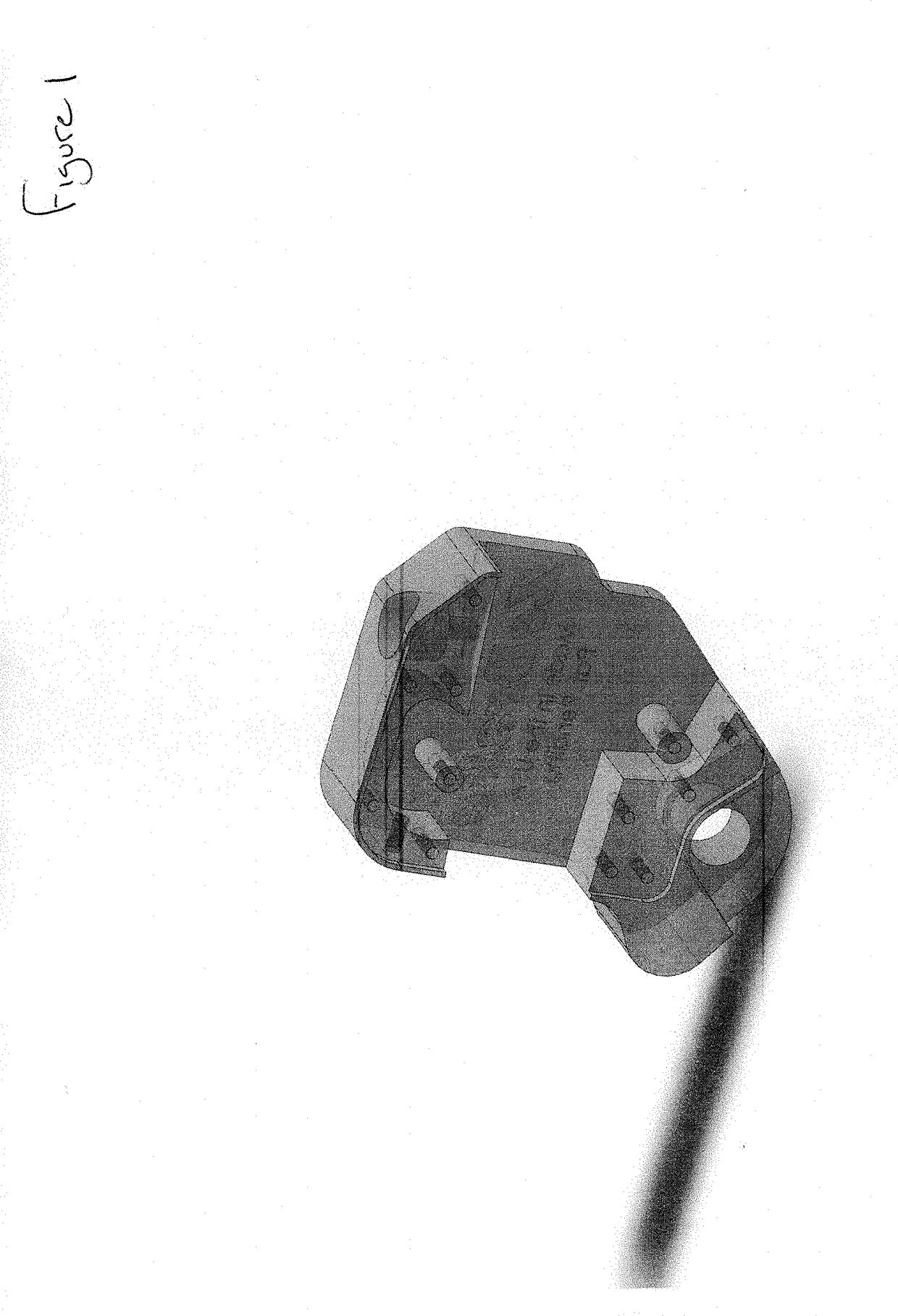
[0007]The brake will work in two ways: either by allowing it to roll to the rider, or by attachment to the zip line. As the rider comes down the zip line with their pulley on the line, their pulley will come in contact with the brake attached to the zip line cable, and the brake will slow them down to a safe speed.
[0008]The brake will consist of a pulley(s) inside a carriage or frame. Attached to the carriage there will be three parts. The first is a fixed pad. The second is the hinged lever. The third is a spring load or weighted hinged lever that will pinch the cable between the fixed pad and rotating pad as the cable slides through the carriage / frame.
[0009]Preferably this device has pads that will be using a camming action to grab the cable after it has been run into by the rider with their pulley. These pads will decrease the space between them as the pads come together to stop or slow the rider down to a safe speed.
BRIEF DESCRIPTION OF DRAWING
[0010]There are 1 figures in the ac...
PUM
 Abstract
Description
Claims
Application Information
 - R&D
- Intellectual Property
- Life Sciences
- Materials
- Tech Scout
- Unparalleled Data Quality
- Higher Quality Content
- 60% Fewer Hallucinations
Browse by: Latest US Patents, China's latest patents, Technical Efficacy Thesaurus, Application Domain, Technology Topic, Popular Technical Reports.
© 2025 PatSnap. All rights reserved.Legal|Privacy policy|Modern Slavery Act Transparency Statement|Sitemap|About US| Contact US: help@patsnap.com