Eureka AIR delivers breakthrough ideas for toughest innovation challenges, trusted by R&D personnel around the world.

Additive manufacturing of composite materials

a composite material and additive manufacturing technology, applied in the direction of manufacturing tools, manufacturing driving means, application layer means, etc., can solve the problems of fdm being somewhat restricted in the variation of shapes that may be fabricated, most cad applications produce errors in output stl files, and no adequate solution to these problems has yet emerged

Active Publication Date: 2017-09-14
MANTIS COMPOSITES INC
View PDF5 Cites 215 Cited by
  • Summary
  • Abstract
  • Description
  • Claims
  • Application Information

AI Technical Summary

Benefits of technology

The invention provides an additive manufacturing apparatus and method for making three-dimensional parts. The apparatus includes a three-dimensional movement system, a rotatable build table, and a nozzle. The nozzle is rotatable in a second plane not parallel to the base and can deposit printer filament onto the build plate. The method involves moving the nozzle in three dimensions and rotating the build plate in a plane parallel to the base to deposit the printer filament onto the build plate. The technical effects of the invention include improved accuracy and efficiency in the manufacturing process and the ability to produce complex parts with fine detail.

Problems solved by technology

Most CAD applications produce errors in output STL files: holes, inverted or inconsistent face normals, self-intersections, noise shells or manifold errors.
FDM is somewhat restricted in the variation of shapes that may be fabricated.
However, none of these additive manufacturing technologies permit the designer to engineer the internal mechanical characteristics of the deposited material of the device in three dimensions, and similarly, they all pose a significant design constraint when subsequently generated layers need to be placed over voids in lower layers or pieces need to be created in these voids that are not supported by already-deposited or formed layers, but that are to be connected to yet-to-be-deposited or formed layers “above.” No adequate solution to these problems has yet emerged.

Method used

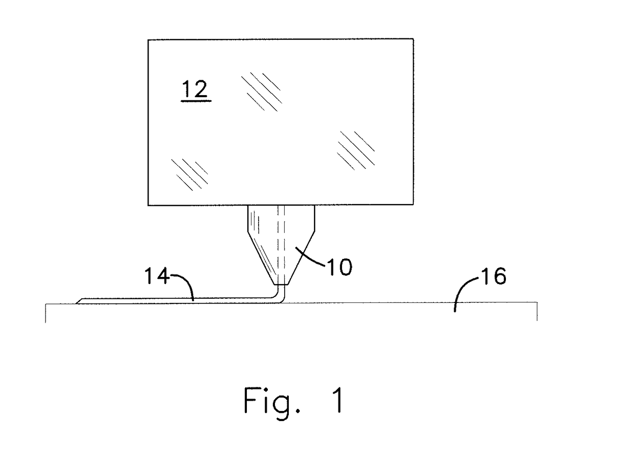
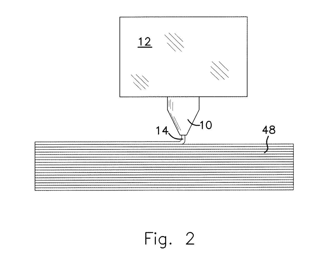

Image

  • Additive manufacturing of composite materials
  • Additive manufacturing of composite materials
  • Additive manufacturing of composite materials

Examples


Embodiment Construction

[0077]The following description is not to be taken in a limiting sense, but is made merely for the purpose of describing the general principles of exemplary embodiments. The scope of the invention should be determined with reference to the claims.

[0078]Reference throughout this specification to “one embodiment,”“an embodiment,” or similar language means that a particular feature, structure, or characteristic described in connection with the embodiment is included in at least one embodiment of the present invention. Thus, appearances of the phrases “in one embodiment,”“in an embodiment,” and similar language throughout this specification may, but do not necessarily, all refer to the same embodiment.

[0079]Furthermore, the described features, structures, or characteristics of the invention may be combined in any suitable manner in one or more embodiments. In the following description, numerous specific details are provided, such as examples of programming, software modules, user select...


PUM

PropertyMeasurementUnit
degree of freedomaaaaaaaaaa
accelerationsaaaaaaaaaa
aspect ratioaaaaaaaaaa

Abstract

An additive manufacturing apparatus having a three-dimensional movement system comprising a first part; a second part coupled to the first part and movable relative to the first part; a third part coupled to the first part and the second part and movable relative to the first part and movable relative to the second part wherein the three-dimensional movement system moves an assembly in three dimensions relative to a base; a rotatable build table coupled to the base, and rotatable in a first plane parallel to the base; and a nozzle, wherein the assembly comprises the nozzle, wherein the nozzle is rotatable in a second plane not parallel to the base, wherein the nozzle comprises an opening for passing a printer filament through the nozzle, and for depositing the printer filament onto the build plate.

Description

[0001]This application claims the benefit of U.S. Provisional Application No. 62 / 306,072, filed Mar. 10, 2016, for ADDITIVE MANUFACTURING OF COMPOSITE MATERIALS which is incorporated in its entirety herein by reference.BACKGROUND OF THE INVENTION[0002]1. Field of the Invention[0003]The present invention relates generally to additive manufacturing systems and methods, and related systems and methods.[0004]2. Discussion of the Related Art[0005]Engineering and design of physical devices (e.g., mechanical devices or parts) has for decades required (often in order to validate or research the performance of designs under real loads, or in real environments) a process of prototyping the devices using available materials. Sometimes these devices are assembled from smaller parts fastened, adhered, welded, or bonded together, and sometimes these devices were hewn from raw materials that are worked, molded, cast, cut or machined.[0006]As advances in technology have progressed, so too have tech...

Claims


Application Information

Patent Timeline
Patent Type & Authority Applications(United States)
IPC IPC(8): B29C67/00B33Y30/00B33Y10/00
CPCB29C67/0074B33Y30/00B33Y10/00B29K2105/12B29C64/209B29C64/241B29C64/118B33Y70/10B33Y40/20
Inventor CHAPIRO, MICHAEL R.DELAY, MICHAEL J.DUNN, RYAN C.ZILAR, DAVID M.
Owner MANTIS COMPOSITES INC
Why Eureka
Eureka Blog
Learn More