
Application Centric Distributed Storage System and Method

a distributed storage and application-centric technology, applied in the field of data storage, can solve the problems of limited sds systems, quality of service, and adherence to legacy storage architecture limitations and volumes,

Inactive Publication Date: 2017-08-31
IOFABRIC
View PDF5 Cites 17 Cited by
  • Summary
  • Abstract
  • Description
  • Claims
  • Application Information

AI Technical Summary

Benefits of technology

The invention is a software-defined storage network that includes multiple storage nodes with data stored on their respective storages devices. The software service determines policies for each volume of data, such as optimizing for latency and input / output operations per second. The service also allows for the placement of data on storage devices based on the policies and the performance characteristics of each storage device. The invention further provides a consistent naming system for each volume and the ability to violate the latency targets for each volume when storing replicated data. The software service can also amalgamate multiple storage services into a single service and make decisions for multiple volumes. Overall, the invention improves the performance and reliability of storage networks.

Problems solved by technology

Current SDS systems are limited in several ways, exemplified by a lack of a sub-volume level of understanding of the data for most of the software features, so capabilities like snapshots and data tiering have to occur at the volume level not at the application or virtual machine level.
This results from their adherence to legacy storage architecture limitations and volumes.
Quality of Service (QoS), if it is available, also is typically limited to a specific volume.
The volume cannot adjust to the needs of the VM.
In reality it is hard to find a storage system without some form of data services.
This limits the system's ability to scale and limits availability.
If these nodes fail all services stop.

Method used

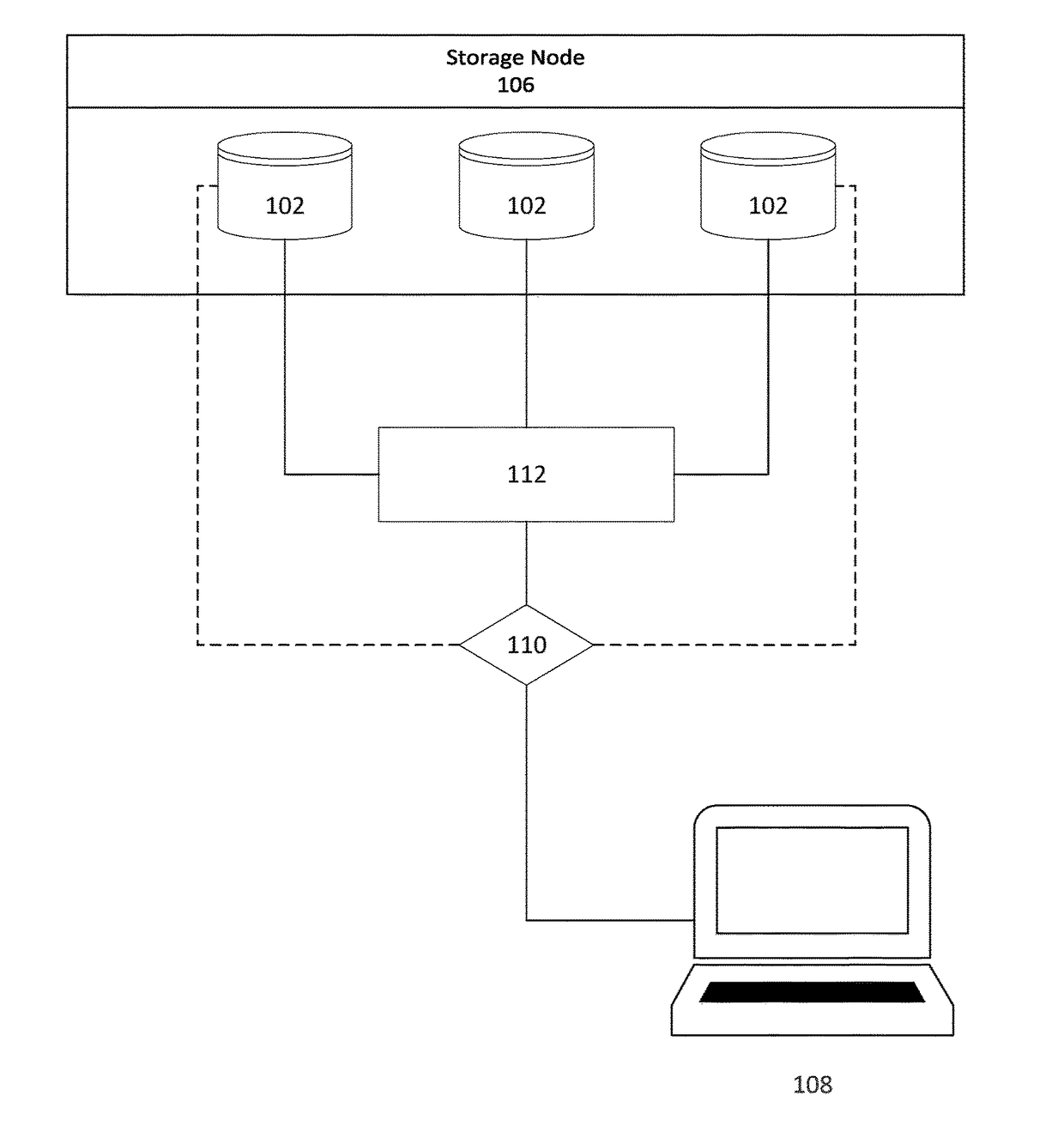
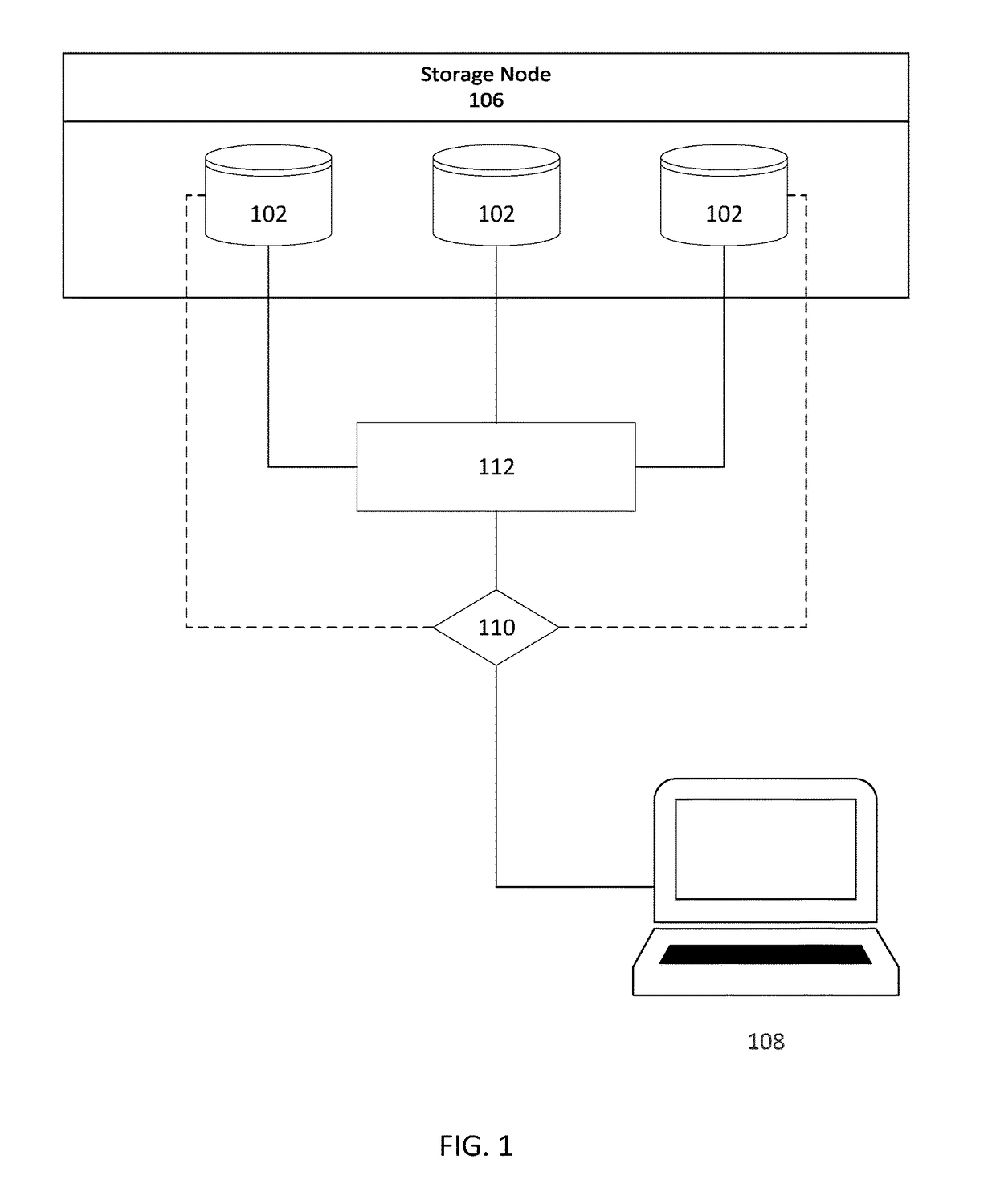
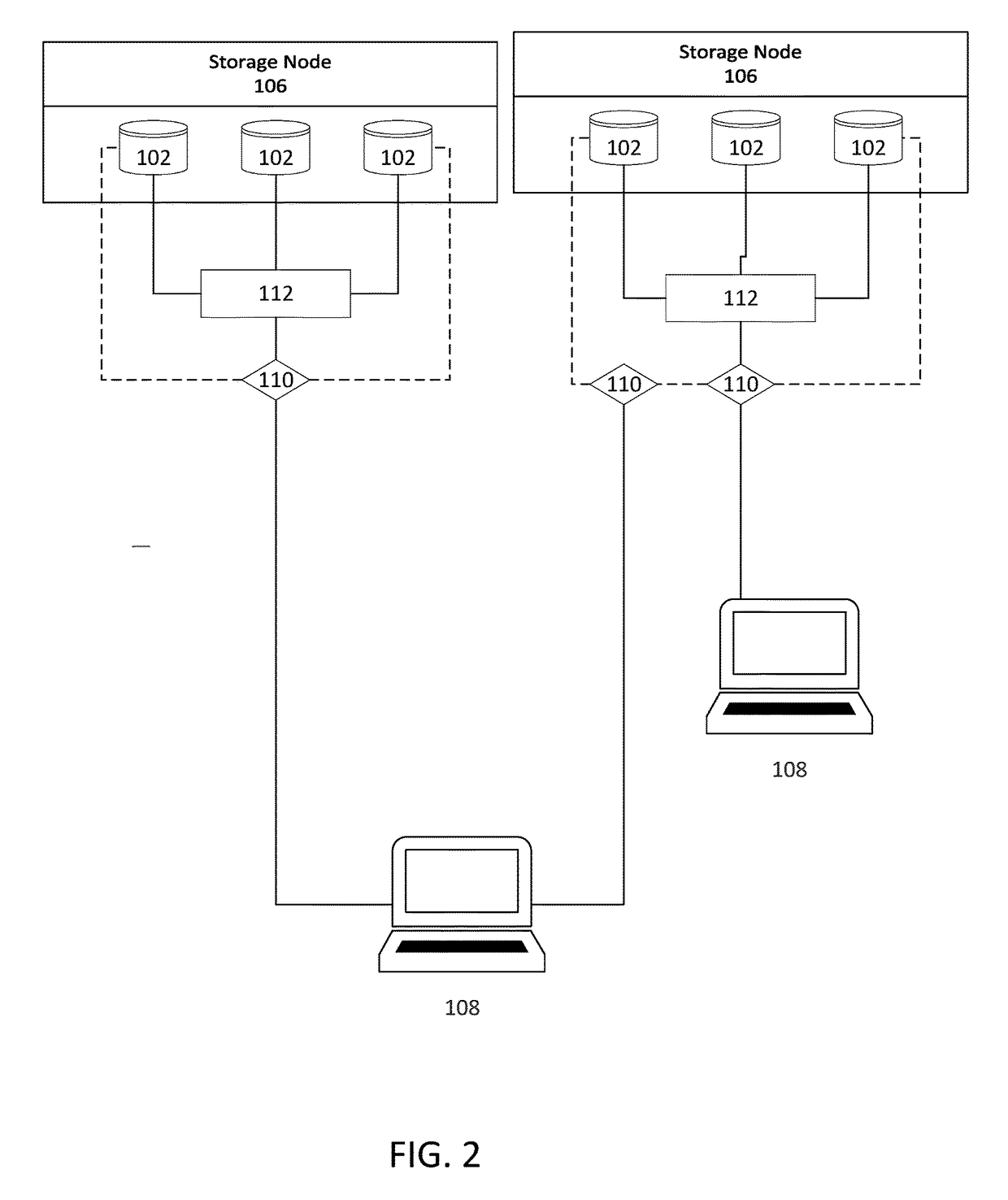

Image

  • Application Centric Distributed Storage System and Method
  • Application Centric Distributed Storage System and Method
  • Application Centric Distributed Storage System and Method

Examples


Embodiment Construction

[0042]For simplicity and clarity of illustration, where considered appropriate, reference numerals may be repeated among the figures to indicate corresponding or analogous elements or steps. In addition, numerous specific details are set forth in order to provide a thorough understanding of the exemplary embodiments described herein. However, it will be understood by those of ordinary skill in the art that the embodiments described herein may be practiced without these specific details. In other instances, well-known methods, procedures and components have not been described in detail so as not to obscure the embodiments generally described herein.

[0043]Furthermore, this description is not to be considered as limiting the scope of the embodiments described herein in any way, but rather as merely describing the implementation of various embodiments as described.

[0044]The embodiments of the systems and methods described herein may be implemented in hardware or software, or a combinati...


PUM


Abstract

A software defined storage network comprising one or more storage nodes, each storage node including a computer processor and one or more data storage devices; the one or more storage devices including a computer readable medium storing data partitioned into one or more volumes; wherein the one or more volumes are visible to at least a subset of the storage nodes and to non-storage nodes on the network; and a computer system in communication with the network having a computer processor executing instructions stored on a computer readable medium to define a plurality of actors providing a storage service; wherein each actor defines a virtual representation of at least one of the volumes and acts as a controller for each of the at least one data storage devices; wherein each of the plurality of actors places data for each volume on the storage devices according to at least one policy.

Description

RELATED APPLICATIONS[0001]This application claims priority from U.S. Provisional Patent Application No. 62 / 045,927, filed Sep. 4, 2014, the contents of which are incorporated herein by reference.TECHNICAL FIELD[0002]This invention relates generally to data storage. More specifically it relates to a system and method of partitioning and storing data on multiple storage resources in a way that enhances latency and protection parameters.BACKGROUND[0003]Software defined storage (SDS) is a concept of computer data storage where the storage of digital data is managed by software rather than the storage hardware itself. Many operations previously managed by each independent hardware device are virtualized into software. Multiple storage hardware elements can be managed through software, with a central interface.[0004]Storage and computational demands and workloads change continuously. Data requirements are constantly increasing. Current SDS systems are limited in several ways, exemplified ...

Claims


Application Information

Patent Timeline
IPC IPC(8): H04L29/08H04L12/879H04L12/24H04L49/901
CPCH04L67/1097H04L41/5009H04L67/1095H04L67/16H04L49/901H04L41/20G06F3/0617G06F3/0607G06F3/061G06F3/0647G06F3/0665G06F3/067H04L67/51
Inventor ZACHARIASSEN, RAYANLAMB, STEVEN
Owner IOFABRIC
Learn More