
Control device, robot, and robot system

a control device and robot technology, applied in the direction of programmed manipulators, programme control, instruments, etc., can solve the problems of cable deficiency and difficulty in improving work efficiency, and achieve the effect of easy drawing and easy drawing work

Active Publication Date: 2017-08-31
SEIKO EPSON CORP
View PDF11 Cites 9 Cited by
  • Summary
  • Abstract
  • Description
  • Claims
  • Application Information

AI Technical Summary

Benefits of technology

The patent describes a system where a control device controls a robot to draw a linear object around a first object. The control device uses information about the positions and sequential numbers of the objects to easily perform the task. The technical effect of this system is that it simplifies the process of drawing a linear object around an object and makes it easier for the control device, robot, and robot system to perform this work.

Problems solved by technology

However, even with such a robot, since the cable is manually drawn around, it is sometimes difficult to improve work efficiency.
In particular, when the cable is not skillfully drawn around, it is likely that a deficiency occurs in the cable.

Method used


Image

  • Control device, robot, and robot system
  • Control device, robot, and robot system
  • Control device, robot, and robot system

Examples


embodiment

[0047]An embodiment of the invention is explained below with reference to the drawings.

Configuration of a Robot System

[0048]First, the configuration of a robot system 1 is explained.

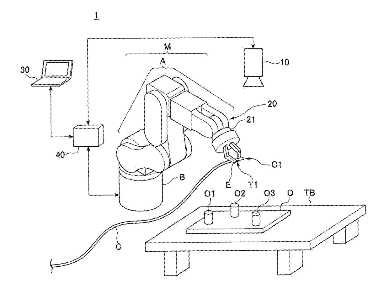
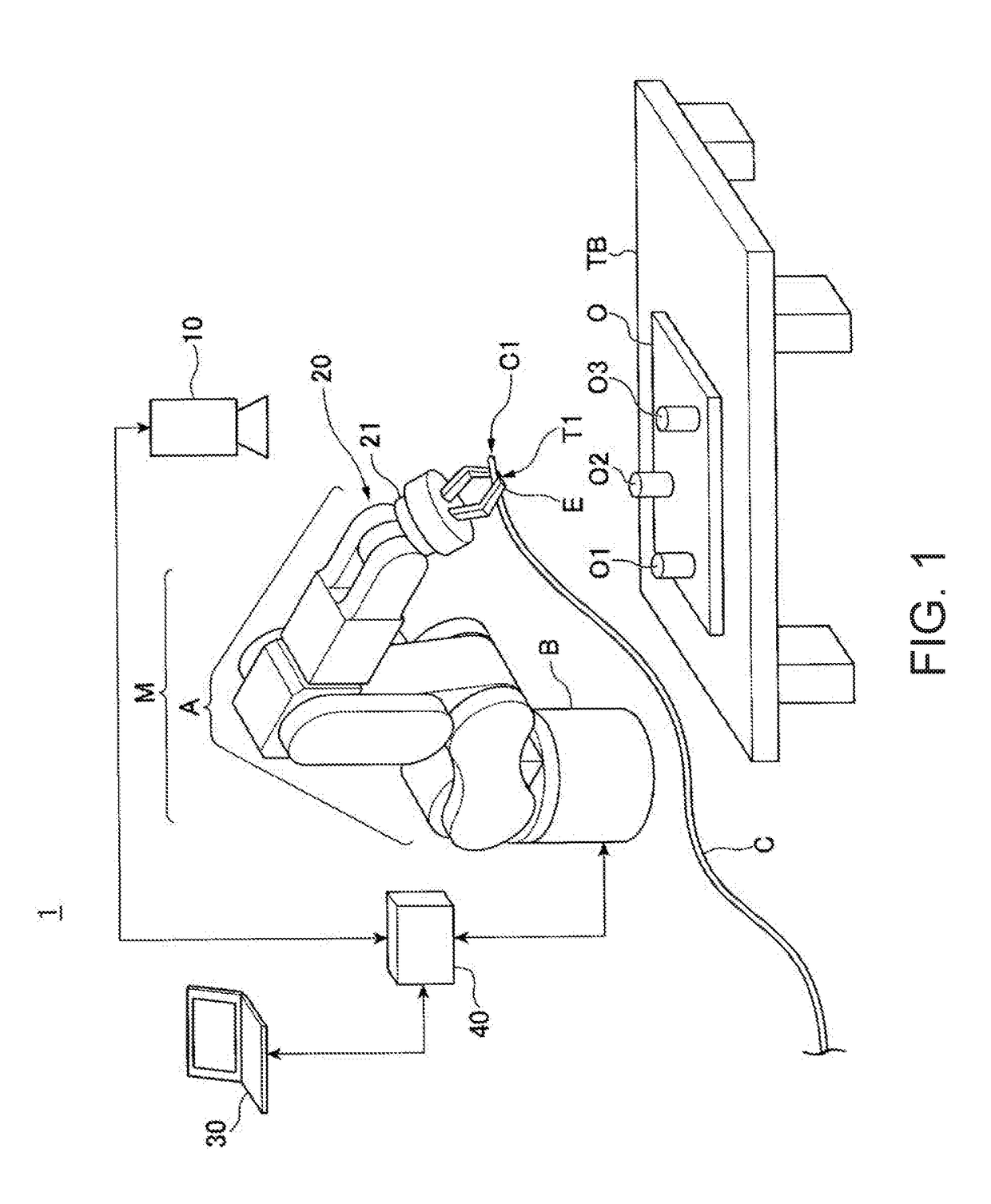
[0049]FIG. 1 is a diagram showing an example of the configuration of the robot system 1 according to this embodiment. The robot system 1 includes an image pickup section 10, a robot 20, an information processing device 30, and a control device 40.

[0050]The image pickup section 10 is a camera including for example, a CCD (Charge Coupled Device) or a CMOS (Complementary Metal Oxide Semiconductor), which is an image pickup device that converts condensed light into an electric signal. In this example, the image pickup section 10 is set in a position where the image pickup section 10 is capable of picking up an image of a range including a region where the robot 20 is capable of performing work.

[0051]The image pickup section 10 is communicatively connected to the control device 40 by a cable. Wired communicat...


PUM


Abstract

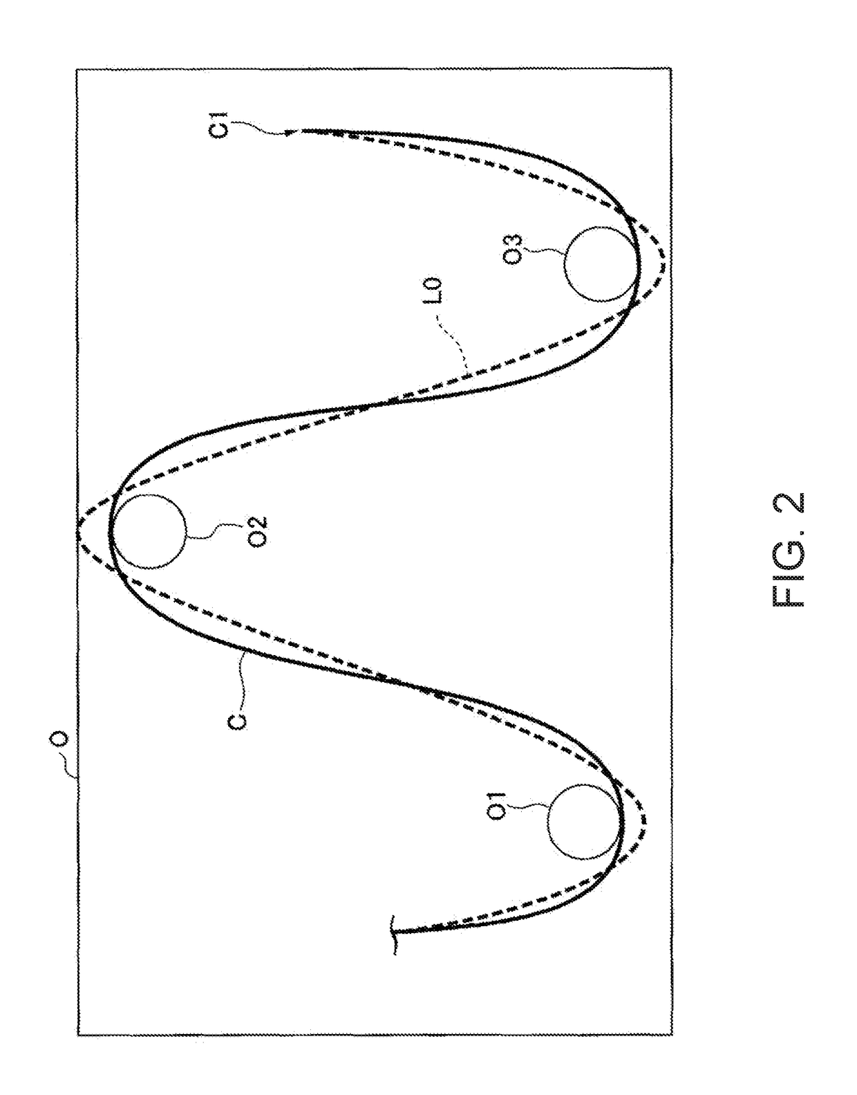
A control device includes a control section configured to control a robot on the basis of first information concerning positions and sequential numbers for drawing a linear object around a first object. The first information is received by a receiving section and displayed on a display section.

Description

BACKGROUND[0001]1. Technical Field[0002]The present invention relates to a control device, a robot, and a robot system.[0003]2. Related Art[0004]Researches and developments for a technique for causing a user to easily draw around a cable have been performed.[0005]Concerning the technique, there is known a robot having structure capable of causing a user to easily perform work for drawing around a cable (see JP-A-2015-160305 (Patent Literature 1)).[0006]However, even with such a robot, since the cable is manually drawn around, it is sometimes difficult to improve work efficiency. A state of the manually drawn-around cable sometimes fluctuates depending on a skill of a person who has drawn around the cable. In particular, when the cable is not skillfully drawn around, it is likely that a deficiency occurs in the cable.SUMMARY[0007]An aspect of the invention is directed to a control device including a control section configured to control a robot on the basis of first information conce...

Claims


Application Information

Patent Timeline
Patent Type & Authority Applications(United States)
IPC IPC(8): B25J9/16B25J13/08
CPCB25J9/1697B25J13/085B25J9/161B25J9/1612G05B2219/37555Y10S901/47G05B2219/39466G05B2219/39446Y10S901/31B25J9/1602B25J13/08B25J19/00B25J9/1679G05B2219/45097
Inventor KOBAYASHI, MASAKAZU
Owner SEIKO EPSON CORP
Learn More