
Method and system for reducing fan noise and electronic device using the same

Active Publication Date: 2017-08-24
CORETRONIC
View PDF0 Cites 9 Cited by
  • Summary
  • Abstract
  • Description
  • Claims
  • Application Information

AI Technical Summary

Benefits of technology

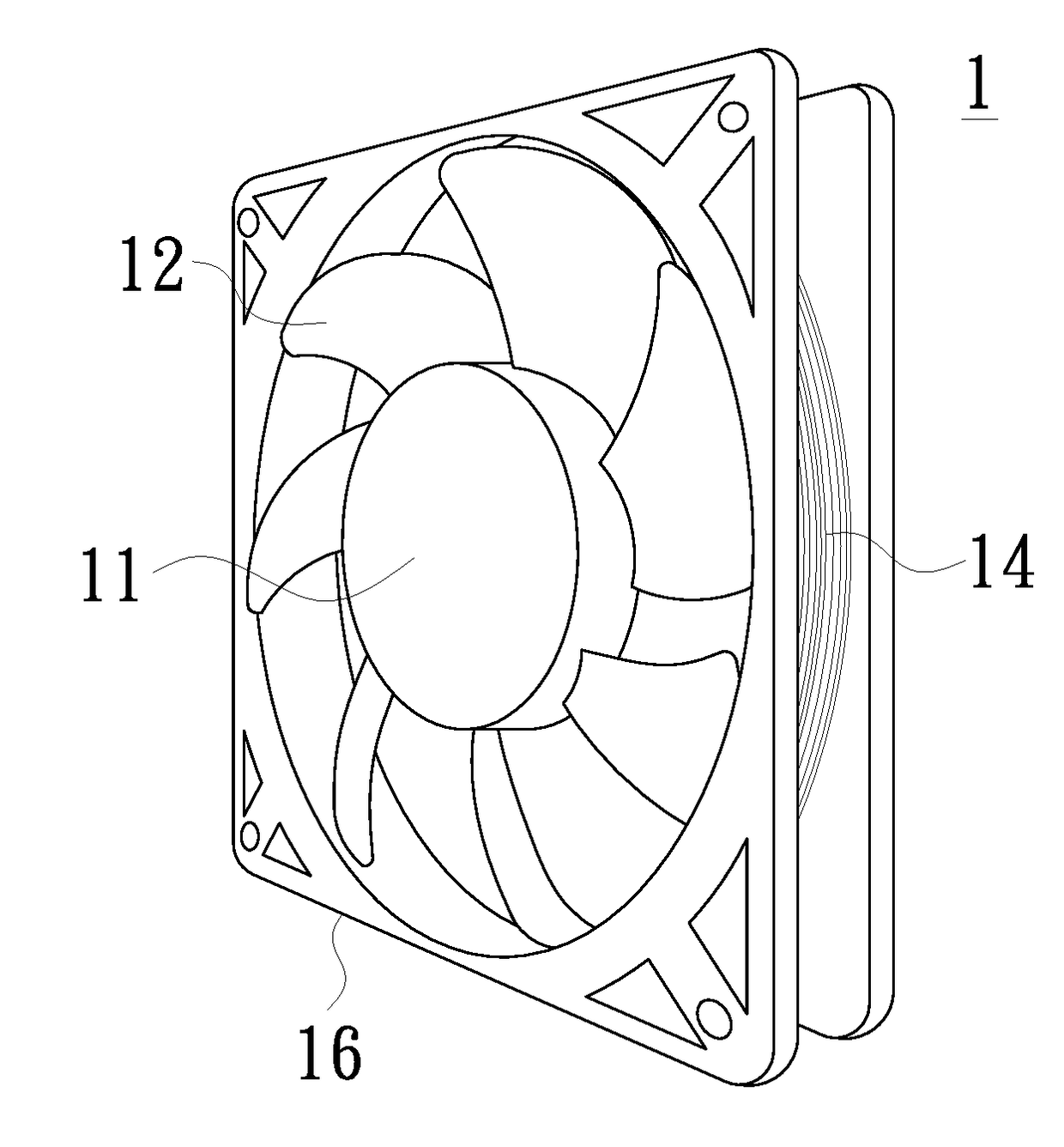
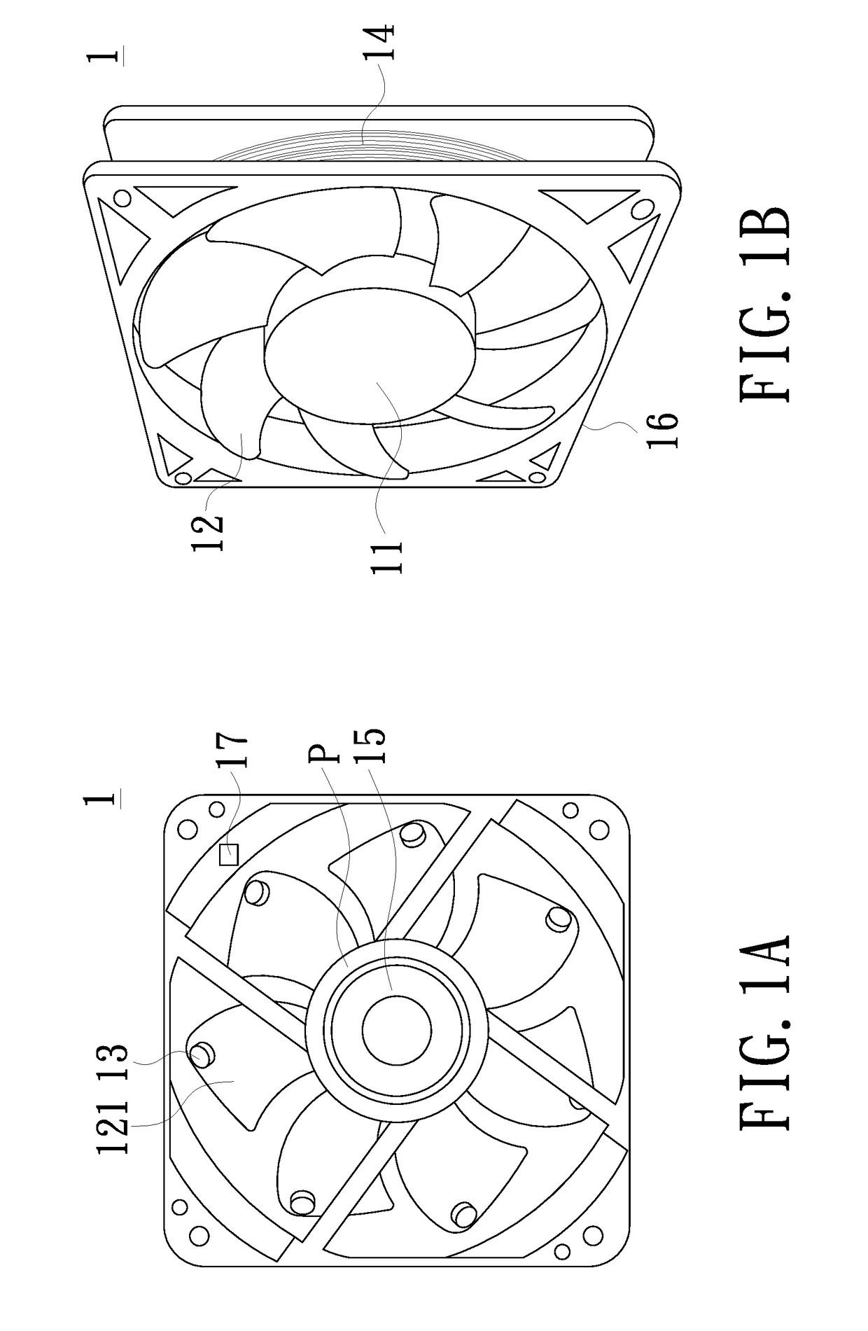
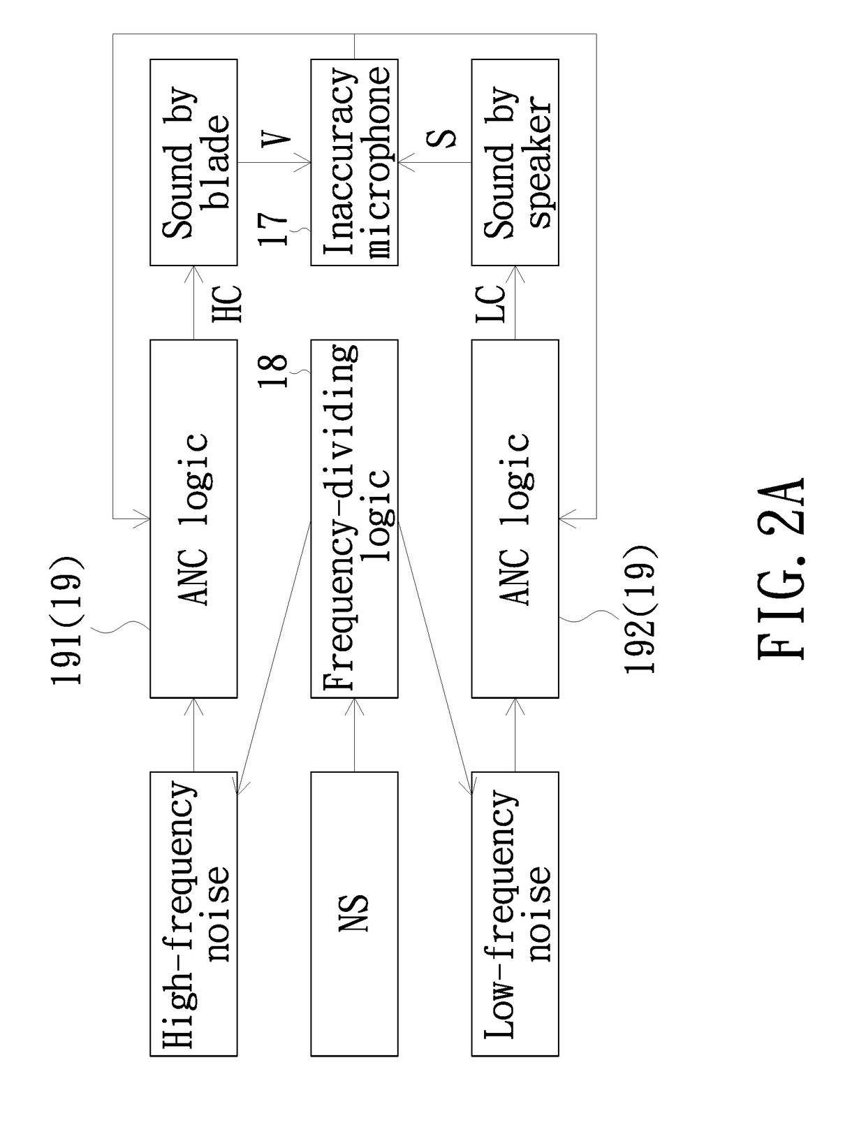
The present invention provides a hybrid active noise-reducing fan structure that utilizes both the speaker and the fan body's vibration at the same time for generating a desired inverse sound source. This improves the effect of active noise-reducing technology. The fan system includes a motor, a fan body, a plurality of blades, a plurality of magnetic-inducing elements, a magnetic field generator, and a noise-reducing sound source device that sends out a noise-reducing sound to counterbalance at least a portion of the noise emitted from the fan body as rotating. The invention also provides a method for reducing fan noise generated in its operation, wherein the fan system includes a plurality of blades that vibrate to produce a vibration sound that counterbalances the high-frequency and low-frequency noise in the fan.

Problems solved by technology

The other positions may occur additive interferences.
However, the noise source and the inverse sound source usually locate at different spatial positions, therefore, the current active noise-reducing technology is only useful to reduce the noise at some specific spatial positions, incapable of reduce the noises in the whole space.
When the noise source's frequency is lower than 1000 Hz, in addition to resonant frequency of several fan body's structure, such a technology has a poor and irregular efficiency in conversion of electrical energy to sonic energy, and thus, it may be hard to use such a structure for effectively reducing fan's low-frequency noise.

Method used


Image

  • Method and system for reducing fan noise and electronic device using the same
  • Method and system for reducing fan noise and electronic device using the same
  • Method and system for reducing fan noise and electronic device using the same

Examples


Embodiment Construction

[0027]In the following detailed description of the preferred embodiments, reference is made to the accompanying drawings which form a part hereof, and in which is shown by way of illustration specific embodiments in which the invention may be practiced. In this regard, directional terminology, such as “top”, “bottom”, “front”, “back”, etc., is used with reference to the orientation of the Figure(s) being described. The components of the invention may be positioned in a number of different orientations. As such, the directional terminology is used for purposes of illustration and is in no way limiting. On the other hand, the drawings are only schematic and the sizes of components may be exaggerated for clarity. It is to be understood that other embodiments may be utilized and structural changes may be made without departing from the scope of the invention. Also, it is to be understood that the phraseology and terminology used herein are for the purpose of description and should not b...


PUM


Abstract

A noise-reducing fan system, comprising a motor, a fan body, a plurality of magnetic-inducing elements, a magnetic field generator and a noise-reducing sound source device, is provided. Here, the fan body is mounted on the motor. The fan body comprises a plurality of blades, on which the plurality of magnetic-inducing elements are disposed, respectively. The magnetic field generator, which may generate a magnetic field, is employed for driving the plurality of magnetic-inducing elements to vibrate the plurality of blades and generate a vibration sound, so that at least one portion of the noise emitted from the fan body as rotating may be counterbalanced. The noise-reducing sound source device is disposed on a predetermined position and may send out a noise-reducing sound, so that the noise-reducing sound may counterbalance at least the other portion of the noise emitted from the fan body as rotating.

Description

CROSS-REFERENCE TO RELATED APPLICATION[0001]This application claims the priority benefit of Taiwan application Ser. No. 105105029, filed on Feb. 19, 2016. The entirety of the above-mentioned patent application is hereby incorporated by reference herein and made a part of this specification.FIELD OF THE INVENTION[0002]The invention relates to an active noise-reducing device and method, and more particularly to a device and method adapted for reducing fan noise.BACKGROUND OF THE INVENTION[0003]An active noise-reducing technology has been developed for a long time. It is possible to reduce, or even eliminate a noise generated from a noise source by an inverse sound source as generated by a speaker. The inverse sound source and the noise source are the same in their volume, but phases of sonic waves are completely contrary to each other, and thus, by wave motion's destructive interference principle, the noise may be reduced, even dispersed.[0004]Since voice is a spherical wave motion, t...

Claims


Application Information

Patent Timeline
IPC IPC(8): G10K11/178
CPCG10K11/1788G10K2210/3025G10K2210/3211G10K2210/129F04D29/325F04D29/388F04D29/665G10K2210/109G10K11/17823G10K11/17857G10K11/17883
Inventor WU, SHANG-HSUANGCHOU, CHIH-CHENG
Owner CORETRONIC
Learn More