
Wind tunnel for human flight

a technology for wind tunnels and human flight, applied in emergency equipment, instruments, transportation and packaging, etc., can solve the problems of large and heavy, large horizontal wind tunnels, and hundreds of metric tons

Active Publication Date: 2017-08-17
INCLINED LABS AB
View PDF0 Cites 11 Cited by
  • Summary
  • Abstract
  • Description
  • Claims
  • Application Information

AI Technical Summary

Benefits of technology

The present invention provides a wind tunnel with an angled section that allows for sustained gliding flight for humans. This is achieved by redirecting the flow of gas in an angle relative to the horizontal plane. Additionally, the invention includes a suspension system connected to the tunnel walls and a quick release system for the person using the wind tunnel. Users may choose to not have the quick release system to minimize the risk of accidental disconnection. The technical effect of this invention is to provide an improved wind tunnel for achieving safe and successful gliding flight.

Problems solved by technology

All in all, the effect of the system design limitations of modern horizontal wind tunnels is that they become very large and very heavy (in the order of 25-50 meters long and tens to hundreds of metric tons in weight), if they are to harbor high flow rates with good quality in a large test section capable of encompassing objects in the size of human bodies.
The vertical wind tunnel has been an important development in these kinds of sports, but now appears limited by its vertical walls, which like a cage prevents flying for real.
In an optimal wind tunnel, a test section with a diameter of 4 m would require a height of 54 m, but the designers and manufacturers of vertical sports wind tunnels have tried various technological workarounds to slightly decrease this value, since building permits for such large edifices are difficult to obtain.
It is often desirable to place a sports and recreation venue accessible to customers, such as in a shopping mall or close to other sports and recreation venues, but this is difficult if the basic design is a very high tower.
The prior-art safety systems are both costly by requiring a safety instructor for each flyer, less safe, by involving a human as an anchor point, and limiting in the possible movements that can be performed by the person using the tunnel.
However, none of these are suitable for use as a safety system for human flyers in an inclined wind tunnel, since no prior art describes a technology permitting the full range of three-dimensional movements desired combined with the strict delimiting properties desired, preventing said flyer from leaving the test section or colliding with its inner structures.

Method used


Image

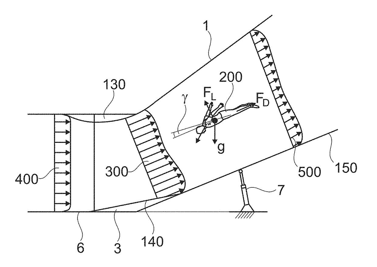
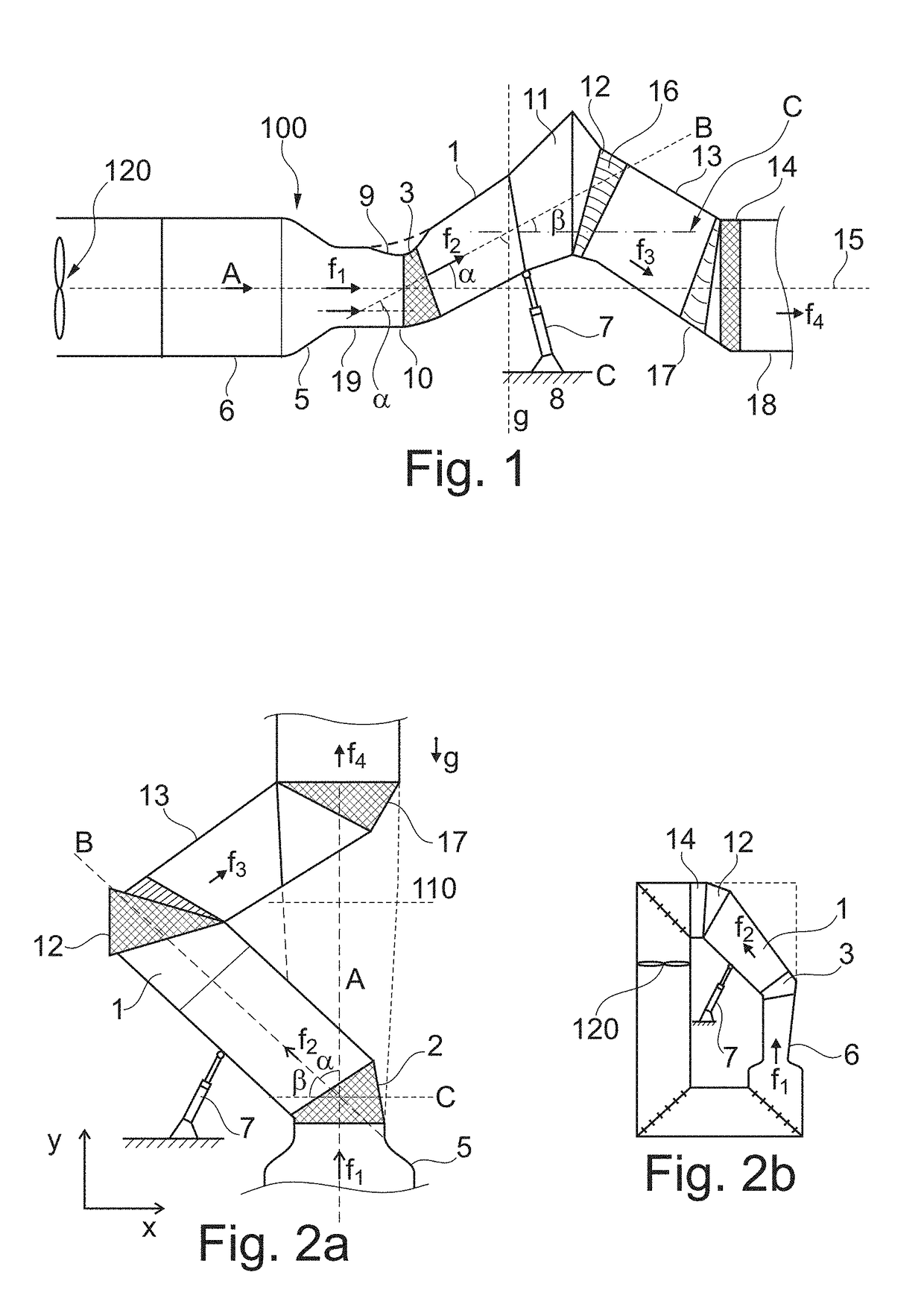
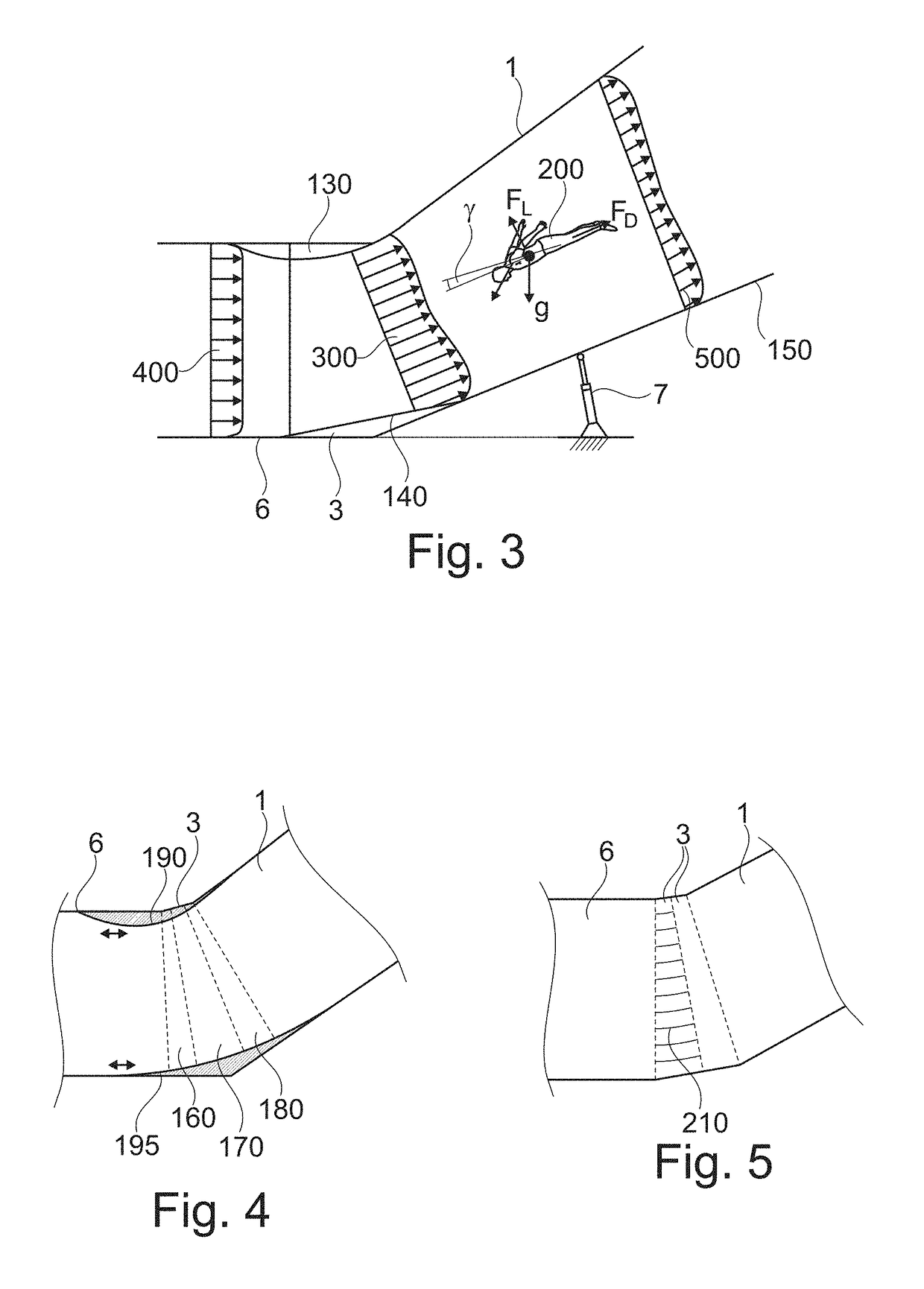
  • Wind tunnel for human flight
  • Wind tunnel for human flight
  • Wind tunnel for human flight

Examples


Embodiment Construction

[0054]The horizontal plane referred to herein is defined as a plane that is perpendicular to the direction of gravitational acceleration, and is denoted by C in FIG. 1.

[0055]The term “stable sustained human flight”, as used herein, refers to a flight for a human that can be performed for an unlimited time and be sustained in the air for as long as desired. The launch and landing may be performed in the same place or in different parts of the test section, and the landing may take place both upstream and downstream of the launch. Thanks to the combination of the inclined test section, the wind speed and the shape and properties of the flow field that serve to allow the human or flyer to remain airborne, the flight itself can be made to last for as long as desired and the flyer can move along the length and width of the test section and still experience suitable aerodynamic conditions for sustained flight. In contrast, some wind tunnels have a fixed launch area and landing area, each ...


PUM


Abstract

A wind tunnel for stable sustained human flight for research or recreation, including a tunnel including first and second portions having first and second central axes, respectively, and a fan to create an air flow in the test section. The second portion is a test section. The first and second central axes are arranged at a first angle with respect to each other. The second central axis is at a second angle of 5°-85° with respect to a horizontal plane. A safety system for an inclined wind tunnel for stable sustained human flight is provided, including an inclined test section of the wind tunnel that is arranged at an angle of 5°-85° with respect to a horizontal plane, a fan to create an air flow in the test section directed from an upstream end towards a downstream end thereof, and a delimiting arrangement arranged at the test section for preventing a person using the test section from leaving it.

Description

TECHNICAL FIELD[0001]The present invention relates to a wind tunnel for human flight for research or recreation, comprising[0002]a tunnel having a first portion with a first central axis and a second portion having a second central axis, wherein the second portion is a test section,[0003]said first central axis and said second central axis being arranged at a first angle with respect to each other, and[0004]at least one fan for creating an air flow in the test section.[0005]The invention also relates to a safety system for an inclined wind tunnel.[0006]BACKGROUND ART[0007]Horizontal wind tunnels have, for over a century, been used to study the flow of air around objects; particularly flying objects. As early as 1901, Orville and Wilbur Wright anchored miniaturized wing profiles in a horizontal tube and exposed them to airflows, to study their airfoil characteristics, drag force and lift force. This simple method to simulate flight without actually flying has played a central role in...

Claims


Application Information

Patent Timeline
Patent Type & Authority Applications(United States)
IPC IPC(8): G01M9/04A63G31/16G09B9/00
CPCG01M9/04A63G2031/005A63G31/16G09B9/00A63G31/00B64D23/00G01M9/02
Inventor WESTMAN, ANTONGEOREN, PETERSTROMBERG, JOHAN
Owner INCLINED LABS AB
Learn More