
Depth Measurement Techniques for a Multi-Aperture Imaging System

a multi-aperture imaging and depth measurement technology, applied in the field of multi-aperture imaging, can solve the problems of not being able to provide the same functionality as a single-lens reflex camera, affecting the image quality produced by the imaging system, and not being able to use the spacious mechanical focus and aperture setting mechanism in such integrated camera applications

Inactive Publication Date: 2017-08-10
DUAL APERTURE INT
View PDF4 Cites 19 Cited by
  • Summary
  • Abstract
  • Description
  • Claims
  • Application Information

AI Technical Summary

Benefits of technology

The patent describes a multi-aperture imaging system that uses infrared light and structured light to calculate depth information from captured images. The system includes an illumination source and an augmented sensor assembly with different subsets of infrared pixels. The system uses blur kernels to determine edge depth information and fill depth information through time of flight analysis or structured light analysis. The system generates a depth map of the scene by combining the edge depth information and the fill depth information. The technical effects of the patent include improved depth information accuracy and improved depth information resolution.

Problems solved by technology

The integration and miniaturization of digital camera technology put serious constraints onto the design of the optical system and the image sensor, thereby negatively influencing the image quality produced by the imaging system.
Spacious mechanical focus and aperture setting mechanisms are not suitable for use in such integrated camera applications.
Although the use of a multi-aperture imaging system provides substantial advantages over known digital imaging systems, such system may not yet provide same functionality as provided in single-lens reflex cameras.
Additionally, as it can be computationally expensive to generate a large number of depth maps for a particular scene, the depth maps are often not available in real time using conventional 3D digital cameras.

Method used


Image

  • Depth Measurement Techniques for a Multi-Aperture Imaging System
  • Depth Measurement Techniques for a Multi-Aperture Imaging System
  • Depth Measurement Techniques for a Multi-Aperture Imaging System

Examples


Embodiment Construction

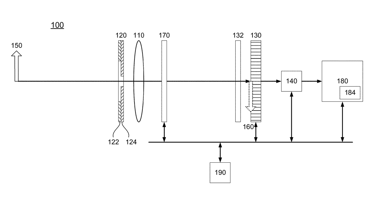
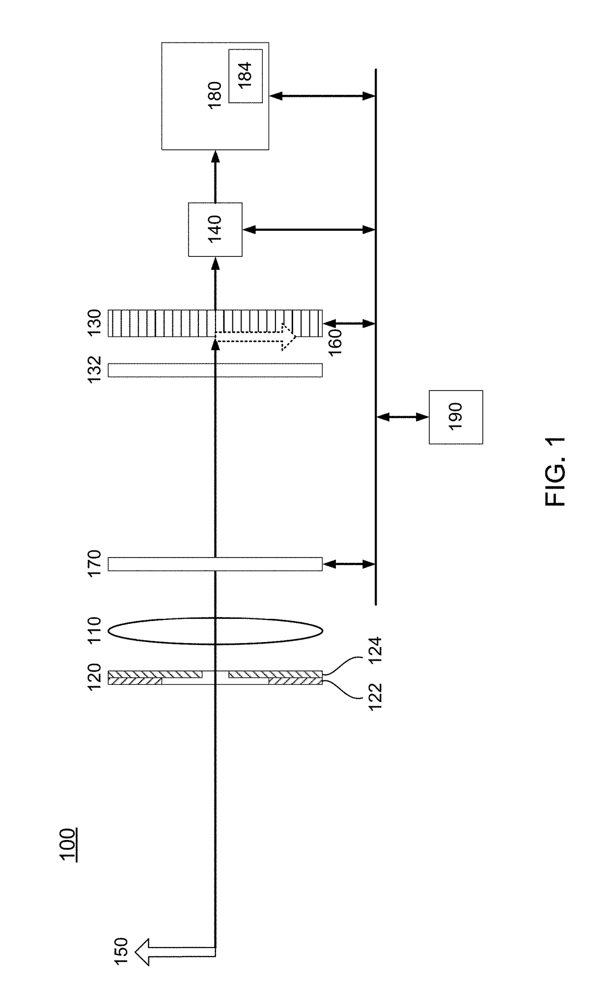
[0038]FIG. 1 is a block diagram of a multi-aperture, shared sensor imaging system 100, also referred to as a multi-aperture imaging system 100, according to one embodiment. The imaging system may be part of a digital camera or integrated in a mobile phone, a webcam, a biometric sensor, image scanner or any other multimedia device requiring image-capturing functionality. The system depicted in FIG. 1 includes imaging optics 110 (e.g., a lens and / or mirror system), a multi-aperture system 120 and an image sensor 130. The imaging optics 110 images objects 150 from a scene onto the image sensor. In FIG. 1, the object 150 is in focus, so that the corresponding image 160 is located at the plane of the sensor 130. As described below, this will not always be the case. Objects that are located at other depths will be out of focus at the image sensor 130.

[0039]The multi-aperture system 120 includes at least two apertures, shown in FIG. 1 as apertures 122 and 124. In this example, aperture 122...


PUM


Abstract

A multi-aperture imaging system determines depth map information. A series of image frames of a scene are captured. The frames include a normal image frame and at least one structured image frame. The multi-aperture imaging system determines edge information of an object in the scene using a deblur technique and the normal image frame. The multi-aperture imaging system determines fill depth information for the object based in part on the at least one structured image frame. The multi-aperture imaging system generates a depth map of the scene using the edge depth information and the fill depth information.

Description

CROSS-REFERENCE TO RELATED APPLICATION(S)[0001]This application claims priority under 35 U.S.C. §119(e) to U.S. Provisional Patent Application Ser. No. 62 / 242,699, “Depth Measurement Techniques for a Multi-Aperture Imaging System,” filed on Oct. 16, 2015. This application is a continuation-in-part of pending U.S. patent application Ser. No. 14 / 949,736, “Generating An Improved Depth Map Using a Multi-Aperture Imaging System,” filed on Nov. 23, 2015, which claims priority to U.S. Provisional Patent Application Ser. No. 62 / 121,182, “Depth Map For Dual-Aperture Camera,” filed on Feb. 26, 2015. The subject matter of all of the foregoing is incorporated herein by reference in their entirety.BACKGROUND[0002]1. Field of the Invention[0003]This disclosure relates generally to multi-aperture imaging and, more particularly, to generating depth maps using multi-aperture imaging.[0004]2. Description of Related Art[0005]The integration and miniaturization of digital camera technology put serious ...

Claims


Application Information

Patent Timeline
IPC IPC(8): H04N13/02
CPCH04N13/0271H04N13/0214H04N13/0217H04N2013/0077H04N13/0257H04N2013/0081H04N13/0253G06T7/571H04N13/25H04N13/254H04N13/271H04N13/214H04N13/218H04N13/257
Inventor WAJS, ANDREW AUGUSTINELEE, DAVID D.RYU, SEUNGOHWOO, TAEKUN
Owner DUAL APERTURE INT
Learn More