
Telecommunications apparatus and methods

a technology applied in the field of telecommunications equipment and methods, can solve the problems of reducing vertical accuracy as compared to horizontal accuracy, unable to determine the location of a terminal device with sufficient vertical accuracy, and gps-based receivers typically less accurate when providing height information

Active Publication Date: 2017-08-03
SONY CORP
View PDF9 Cites 18 Cited by
  • Summary
  • Abstract
  • Description
  • Claims
  • Application Information

AI Technical Summary

Benefits of technology

The patent describes an invention that has various benefits. It provides a way to introduce a new technology or improve an existing technology. The topic of the patent text covers the general introduction and the specific details of the invention, which can be found by reading the accompanying drawings. Overall, the technology described in this patent provides some benefits to improve or advance certain aspects of technology.

Problems solved by technology

However, it is well recognized that GPS-based receivers are typically less accurate when providing height information.
Consequently, it can be expected that existing schemes for determining a terminal device's position may be unable to determine the location of a terminal device with sufficient vertical accuracy to allow the floor of a building in which the terminal device is located to be reliably determined.
The issue of reduced vertical accuracy as compared to horizontal accuracy is especially significant in the context of seeking to determine on which floor of a building a terminal device is located because GPS-based receivers generally work less well in buildings due to increased signal penetration losses.
Furthermore, the consequence of an inaccurate height determination will often be more significant than an inaccurate horizontal position because it will generally take an emergency responder more time to move from one floor to another floor when it is realised there is an error in vertical determination than to move from one room to another room on the same floor when there is an error in horizontal determination.

Method used


Image

  • Telecommunications apparatus and methods
  • Telecommunications apparatus and methods
  • Telecommunications apparatus and methods

Examples


Embodiment Construction

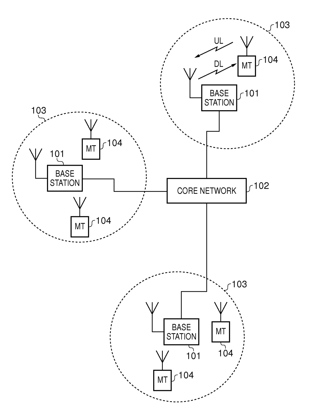
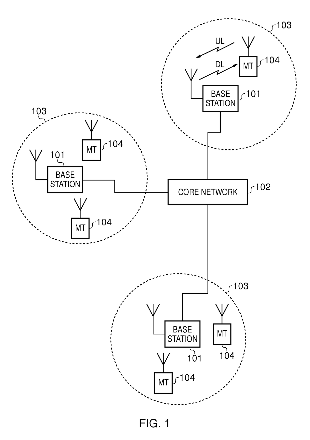
[0027]FIG. 1 provides a schematic diagram illustrating some basic functionality of a mobile telecommunications network / system 100 operating in accordance with LTE principles and which may be adapted to implement embodiments of the disclosure as described further below. Various elements of FIG. 1 and their respective modes of operation are well-known and defined in the relevant standards administered by the 3GPP (RTM) body and also described in many books on the subject, for example, Holma H. and Toskala A [2]. It will be appreciated that operational aspects of the telecommunications network which are not specifically described below may be implemented in accordance with any known techniques, for example according to the relevant standards.

[0028]The network 100 includes a plurality of base stations 101 connected to a core network 102. Each base station provides a coverage area 103 (i.e. a cell) within which data can be communicated to and from terminal devices 104. Data is transmitte...


PUM


Abstract

Methods and apparatus for determining an altitude for a terminal device operating in a wireless telecommunications network including the terminal device and another network entity. The terminal device measures an indication of barometric pressure in its vicinity using a barometric sensor. The other network entity establishes calibration information, for the barometric pressure measurement, including a reference barometric pressure for a reference altitude and may come from a barometric pressure measurement at the other network entity or from meteorological data provided to the other network entity. The altitude relative to the reference altitude may then be determined from the difference between the barometric pressure measured by the terminal device and the reference barometric pressure, by the terminal device after receiving the calibration information from the other network entity and / or by the other network entity after receiving an indication of the barometric pressure measured by the terminal device.

Description

BACKGROUND[0001]Field[0002]The present disclosure relates to telecommunications apparatus and methods. In particular, certain embodiments relate to apparatus and methods for determining the height (i.e. altitude / elevation) of a terminal device operating in a wireless telecommunications system.[0003]Description of Related Art[0004]The “background” description provided herein is for the purpose of generally presenting the context of the disclosure. Work of the presently named inventor, to the extent it is described in this background section, as well as aspects of the description which may not otherwise qualify as prior art at the time of filing, are neither expressly or impliedly admitted as prior art against the present invention.[0005]Mobile communication systems have evolved over the past ten years or so from the GSM System (Global System for Mobile communications) to the 3G system and now include packet data communications as well as circuit switched communications. The third gen...

Claims


Application Information

Patent Timeline
IPC IPC(8): G01C5/06H04W4/02
CPCH04W4/025G01C5/06
Inventor MORIOKA, YUICHI
Owner SONY CORP
Learn More