Engine control device

Active Publication Date: 2017-07-27
DENSO CORP
View PDF0 Cites 1 Cited by
  • Summary
  • Abstract
  • Description
  • Claims
  • Application Information

AI Technical Summary

Benefits of technology

The engine control device described in this patent allows for more frequent automatic engine stops and reduces fuel consumption by detecting whether the engine can restart automatically at the initial engine start time. This results in increased opportunities for automatic engine stops and lower fuel consumption.

Problems solved by technology

However, the conventional engine control device disclosed in the patent document 1 inhibits the execution of the automatic engine stop process in the decelerating state at least until the automatic engine stop process at the first time has been executed in the vehicle stopped state.
Accordingly, the conventional engine control device cannot execute the automatic engine stop process in the decelerating state until the automatic engine stop process at the first time has been executed in the vehicle stopped state even if there is a possible opportunity to correctly execute the automatic engine stop process in the decelerating state.

Method used


Image

  • Engine control device
  • Engine control device
  • Engine control device

Examples


first exemplary embodiment

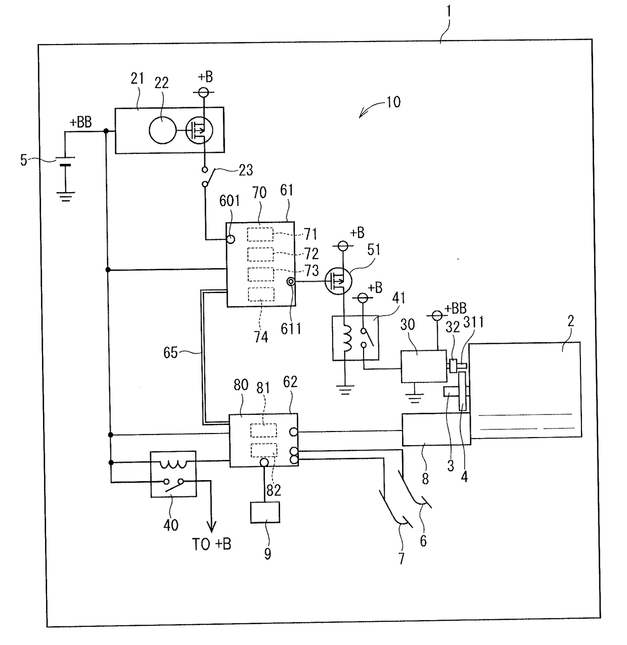
[0036]A description will be given of an engine control device according to a first exemplary embodiment and a vehicle 1 on which the engine control device is mounted with reference to FIG. 1 to FIG. 6.

[0037]FIG. 1 is a schematic view showing the engine control device 10 according to the first exemplary embodiment and the vehicle 1 equipped with the engine control device 10. As shown in FIG. 1, the engine control device 10 according to the first exemplary embodiment is applied to the vehicle 1. The vehicle 1 has an internal combustion engine (hereinafter, the engine 2), a battery 5, and the engine control device 10 according to the first exemplary embodiment.

[0038]The engine 2 is a four cylinder gasoline engine using gasoline fuel, for example. The engine 2 provides an output torque through its driving shaft 3. Wheels (omitted from drawings) of the vehicle 1 are driven by the output torque of the engine 2 transmitted through the driving shaft 3, and the vehicle moves forward or backw...

second exemplary embodiment

[0182]A description will be given of the engine control device 10 according to the second exemplary embodiment with reference to FIG. 7.

[0183]FIG. 7 is a schematic view showing the engine control device 10 according to the second exemplary embodiment and the vehicle 1 equipped with the engine control device 10.

[0184]The engine control device 10 according to the second exemplary embodiment shown in FIG. 7 has the initial engine start detection section which is different in structure from that according to the first exemplary embodiment. Other components between the second exemplary embodiment and the first exemplary embodiment are same.

[0185]The engine control device 10 according to the second exemplary embodiment has a key starter 25. The key starter 25 has a key-insertion hole 26, a terminal 251, an ACC contact 252, an IG contact 253 and a START contact 254.

[0186]As shown in FIG. 7, the driver of the vehicle 1 inserts the key 27 into the key-insertion hole 26 of the key starter 25....

third exemplary embodiment

[0195]A description will be given of the engine control device 10 according to the third exemplary embodiment with reference to FIG. 8.

[0196]FIG. 8 is a schematic view showing the engine control device 10 according to the third exemplary embodiment and the vehicle 1 equipped with the engine control device 10. As shown in FIG. 8, the number of components forming the engine control device 10 according to the third exemplary embodiment is more than the number of components forming the engine control device 10 according to the first exemplary embodiment. That is, the engine control device 10 according to the third exemplary embodiment further has a low voltage side driver 52 when compared with the structure of the engine control device 10 according to the first exemplary embodiment.

[0197]For example, the low voltage side driver 52 is a n-MOS switching element. The low voltage side driver 52 is arranged at a low voltage side when compared with the relay 41. A drain of the low voltage sid...


PUM


Abstract

In an engine control device, an automatic engine stop control section automatically stops an engine operating when an automatic engine stop condition is satisfied. An engine start control section supplies electric power to a starter to drive the starter when receiving an initial engine start intention signal transmitted from a push starter and when an automatic engine start condition has been satisfied. An engine start completion detection section detects whether the engine start of the engine has finished. An automatic engine stop permission section permits the automatic engine stop control section to stop the engine operating when the automatic engine stop permission section detects that the engine start has finished at a timing when the engine start control section has started the engine after receiving an initial engine start intention detection signal transmitted from the push starter.

Description

CROSS-REFERENCE TO RELATED APPLICATION[0001]This application is related to and claims priority from Japanese Patent Application No. 2016-012331 filed on Jan. 26, 2016, the contents of which are hereby incorporated by reference.BACKGROUND OF THE INVENTION[0002]1. Field of the Invention[0003]The present invention relates to engine control devices capable of controlling the operation of an internal combustion engine mounted on a vehicle.[0004]2. Description of the Related Art[0005]There have been known and used vehicles equipped with an engine control device capable of providing an idling reduction function (or an idle stop function). The engine control device has the idling reduction function which automatically stops the operation of an internal combustion engine (hereinafter, the engine) when a predetermined engine stop condition is satisfied.[0006]A patent document 1, Japanese patent No. 5609826 discloses a conventional engine control device. This conventional engine control device...

Claims


Application Information

Patent Timeline
IPC IPC(8): F02D41/04F02N11/08F02D41/06
CPCF02D41/042F02D41/065F02N11/0851F02N11/0862F02N11/0803F02D29/02F02N11/0818F02N11/087F02N15/067F02N2200/022F02N2300/2011F02N2300/304Y02T10/40
Inventor OKAMIYA, MINORU
Owner DENSO CORP
Why Eureka
Try Eureka