
Imaging and display system for guiding medical interventions

Active Publication Date: 2017-07-20
THE UNIVERSITY OF AKRON
View PDF12 Cites 159 Cited by
  • Summary
  • Abstract
  • Description
  • Claims
  • Application Information

AI Technical Summary

Benefits of technology

The present invention provides an imaging and display system for guiding medical interventions that can capture and display pre-operative images and intra-operative images simultaneously on a wearable display. The system can also communicate with other devices, such as ultrasound imaging systems, and can provide a composite image of the pre-operative and intra-operative images. The system can also include a peripheral interface for communication with other peripherals, such as spectrometers. The technical effects of the invention include improved guidance and precision during medical interventions and the ability to capture and display images simultaneously.

Problems solved by technology

Medical professionals, such as surgeons, face enormous challenges during surgical interventions.
However, conventional surgical navigation, intra-operative imaging-based medical guidance, and pathology-based medical guidance techniques have a variety of drawbacks.
For example, because conventional surgical navigation is based on pre-operative images, it is therefore unable to accommodate the tissue deformation that occurs at the surgical site during the performance of the surgical procedure; and is unable to provide real-time imaging updates.
In addition, real-time intra-operative imaging surgical guidance techniques provides a limited field of view of the surgical site to the surgeon, and is unable to provide comprehensive, global, whole-body anatomical information of a patient, which makes such surgical guidance techniques difficult to use in some instances.
Furthermore, pathology / microscopy-based techniques are unable to sample all surgical sites, and also requires a substantial amount of time to complete.

Method used


Image

  • Imaging and display system for guiding medical interventions
  • Imaging and display system for guiding medical interventions
  • Imaging and display system for guiding medical interventions

Examples


Embodiment Construction

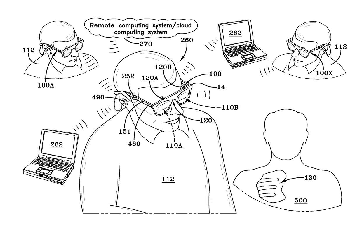
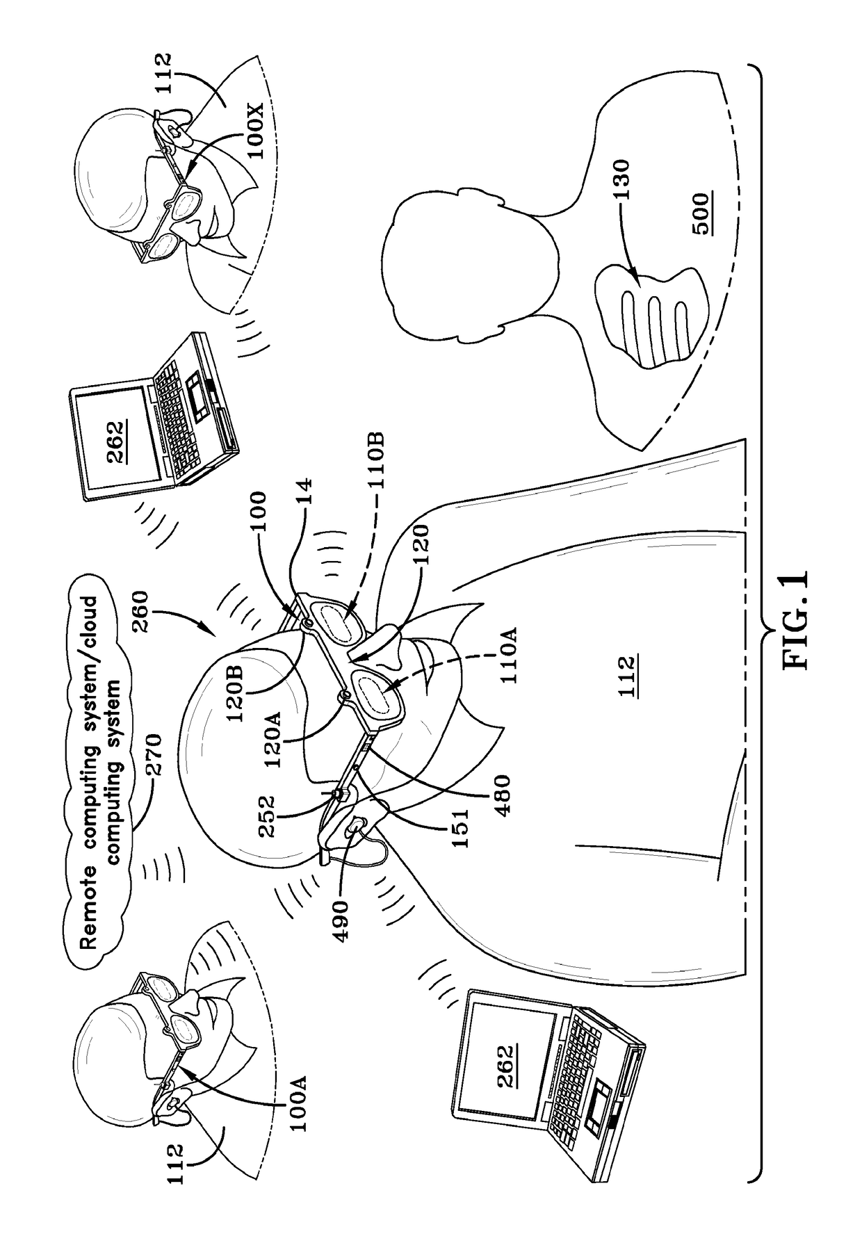
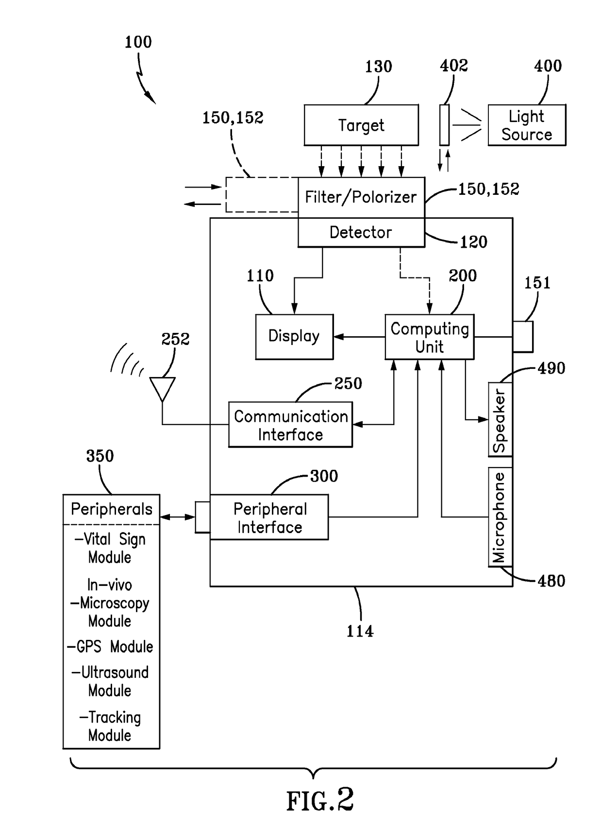
[0055]An imaging and display system for guiding medical interventions is generally referred to by reference numeral 100, as shown in FIG. 1 of the drawings. The system 100, shown in detail in FIG. 2, includes a display 110, which may comprise any suitable display, such as a wearable display that is configured for being attached to and worn by a user 112. For example, the wearable display 110 may be included as part of a goggle-type wearable device 114 shown in FIG. 1, which comprises a wearable goggle or eye-piece frame that carries the display 110.

[0056]In one aspect, the display 110 may comprise a single display element suitable for providing a single, continuous display that provides a single display surface that encompasses the totality of the user's field of view, or portion thereof. Alternatively, multiple separate display elements, may be used by the display, such as a dedicated right and a dedicated left display, such as in the case of a stereoscopic display, which provides ...


PUM


Abstract

An imaging and display system for guiding medical interventions includes a wearable display, such as a goggle display, for viewing by a user. The display presents a composite, or combined image that includes pre-operative surgical navigation images, intraoperative images, and in-vivo microscopy images or sensing data. The pre-operative images are acquired from scanners, such as MRI and CT scanners, while the intra-operative images are acquired in real-time from a camera system carried by the goggle display for imaging the patient being treated so as to acquire intraoperative images, such as fluorescence images. A probe, such as a microscopy probe or a sensing probe, is used to acquire in-vivo imaging / sensing data from the patient. Additionally, the intra-operative and in-vivo images are acquired using tracking and registration techniques to align them with the pre-operative image and the patient to form a composite image for display by the goggle display.

Description

CROSS-REFERENCE TO RELATED APPLICATION[0001]This application claims the benefit of U.S. Provisional Application No. 61 / 942,666 filed on Feb. 21, 2014, the content of which is incorporated herein by reference.TECHNICAL FIELD[0002]The present invention generally relates to imaging and display systems. Particularly, the present invention relates to an imaging and display system for guiding medical interventions, such as surgical interventions. More particularly, the present invention relates to a wearable imaging and display system for guiding medical interventions by the simultaneous display of pre-operative surgical navigation images, real-time intra-operative images, and in-vivo, microscopy imaging and sensing data.BACKGROUND OF THE INVENTION[0003]Medical professionals, such as surgeons, face enormous challenges during surgical interventions. To assist surgeons in their efforts to provide efficient and effective surgical care, three independent and separate approaches for guiding me...

Claims


Application Information

Patent Timeline
IPC IPC(8): A61B90/00A61B90/20
CPCA61B90/37A61B90/20A61B2090/365A61B2090/3735A61B2090/3762A61B2090/372A61B2090/502A61B90/36A61B2034/2048A61B2034/2055A61B2090/309A61B90/00A61B2090/371A61B2034/2051A61B2090/3941G16H20/40G16H40/63
Inventor LIU, YANG
Owner THE UNIVERSITY OF AKRON
Learn More