
Manufacturing device for micro-needle

Active Publication Date: 2017-07-06
RAPHAS
View PDF4 Cites 1 Cited by
  • Summary
  • Abstract
  • Description
  • Claims
  • Application Information

AI Technical Summary

Benefits of technology

The present patent is about a device for manufacturing small needles that can be used to make patch sheets. The device has two main technical effects. Firstly, it has a strong fixing mechanism for the patch sheet, which ensures accuracy in its positioning. Secondly, it helps to maximize space application by reducing the movement range of the stage. These technical effects are important for improving the precision and efficiency of the manufacturing process for microneedles.

Problems solved by technology

However, when a microneedle is manufactured with the molding method, there is a problem in that the microneedle is damaged in the course of separating a product at which the microneedle is formed from a mold.
Also, there is a problem in that strength of the microneedle manufactured with the molding method is relatively weak.
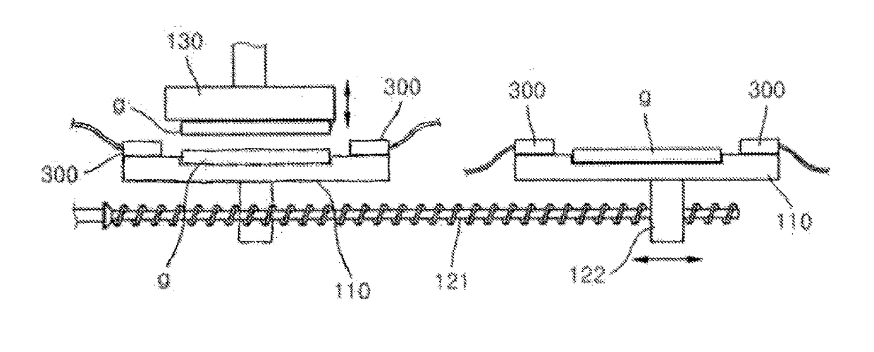
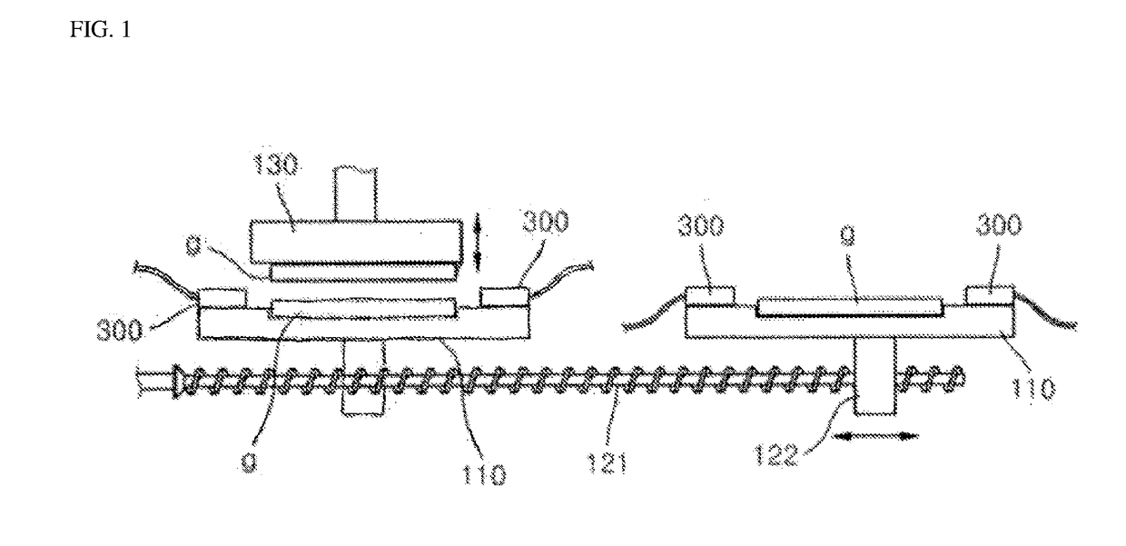
Further, in the manufacturing device for a microneedle of the related art of FIG. 1, inefficiency regarding an aspect of space application exists owing to a large movement range of the horizontal movement stage 110.

Method used


Image

  • Manufacturing device for micro-needle
  • Manufacturing device for micro-needle
  • Manufacturing device for micro-needle

Examples


Embodiment Construction

[0038]The following detailed description with respect to the present disclosure will be described with reference to the accompanying drawings illustrating as examples of specific embodiments which can implement the present disclosure. These embodiments will be fully described in detail for allowing a person skilled in the art to implement the present disclosure. It should be understood that various embodiments of the present disclosure are different from each other, but they are not to be exclusive mutually. For example, specific shapes, structures, and features disclosed herein may be implemented by another embodiment in association with one embodiment without departing from the spirit and scope of the present invention. Also, it should be understood that positions and arrangements of respective components disclosed in each embodiment may be modified without departing from the spirit and scope of the present disclosure. The detailed description to be disclosed later, therefore, is ...


PUM

PropertyMeasurementUnit
Viscosityaaaaaaaaaa

Abstract

A manufacturing device for a microneedle includes an upper plate stage, a lower plate stage disposed in horizontally parallel with the upper plate stage, a rotating device configured to rotate and move the upper plate stage over the lower plate stage, and a first cylindrical type actuator configured to vertically move the lower plate stage in a state in which the upper plate stage has been rotated and moved over the lower plate stage by the rotating device. The first cylindrical type actuator may upwardly and downwardly move so as to be able to stretch a viscous composition in a vertical direction in a state in which a contacting to the viscous composition is performed, wherein the viscous composition is applied on both of a patch sheet seated on the upper plate stage and a patch sheet seated on the lower plate stage, or is applied on one of them.

Description

CROSS-REFERENCE TO RELATED APPLICATIONS[0001]This application claim priority to Korean Patent Application No. 2015-0189855 filed on Dec. 30, 2015, the entire contents of which are hereby incorporated by reference.BACKGROUND[0002]1. Technical Field[0003]The present disclosure relates to a manufacturing device for a microneedle.[0004]2. Description of the Related Art[0005]A microneedle is mainly manufactured with a molding method in the related art. A molding type manufacturing device for a microneedle is disclosed in, for example, Korean Patent Application Publication No. 10-2011-0012986, and the like.[0006]However, when a microneedle is manufactured with the molding method, there is a problem in that the microneedle is damaged in the course of separating a product at which the microneedle is formed from a mold. Also, there is a problem in that strength of the microneedle manufactured with the molding method is relatively weak.[0007]To address the problems of such a molding type manu...

Claims


Application Information

Patent Timeline
IPC IPC(8): B29C55/00B29C37/00B29C33/30A61M37/00
CPCB29C55/00A61M37/0015B29C37/00B29L2031/7544B29C2037/90B29K2105/0058B29C33/30B81C1/00111A61M2037/0046A61M2037/0053
Inventor KIM, HONG KEEKIM, JUNG DONGBAE, JUNG HYUNLEE, YANG GIPARK, SO HYUNJEONG, DO HYEON
Owner RAPHAS
Learn More