
Systems and methods to detect and recover from a loop in an ethernet ring protected network

a technology of ethernet ring and loop, applied in the field of network working systems and methods, can solve problems such as data packet loops, loops in ethernet rings, and bring down not only the ring involved but sometimes the line card/system

Active Publication Date: 2017-06-22
CIENA
View PDF8 Cites 16 Cited by
  • Summary
  • Abstract
  • Description
  • Claims
  • Application Information

AI Technical Summary

Benefits of technology

The patent describes a method and apparatus for detecting loops in an Ethernet network and automatically implementing recovery actions to prevent network failure. The method involves transmitting a loop detection frame on both ports of a node in the network and monitoring the reception of the frame. If a loop is detected, the apparatus can activate a forced switch or shut down the affected port to prevent network failure. The loop detection service can be provided as an Ethernet Virtual Local Area Network (E-VLAN) service on the network. The technical effect of this patent is to enhance the reliability and resilience of Ethernet networks by detecting and preventing loops in real-time.

Problems solved by technology

By virtue of its topology, ring based networks, which have learning and flooding on the Layer 2 Ethernet domain, are prone to data packet loops.
However, during deployment and operation, provisioning related aspects, hardware related aspects, and protocol related aspects all have the potential to cause loops in Ethernet rings.
The hardware related aspects can include issues with blocking Application Programming Interfaces (APIs), issues with forwarding / dropping of Ring-Automatic Protection Switching (R-APS) control frames, issues with flooding / learning behavior, and the like.
These adverse conditions can bring down not only the rings involved but sometimes the line card / system and the network as well.
Detection of a loop using MAC movement requires a centralized MAC learning analysis which may not be possible in distributed systems.
Also, some loops may occur that do not exhibit this condition and cannot be detected by MAC movement.

Method used


Image

  • Systems and methods to detect and recover from a loop in an ethernet ring protected network
  • Systems and methods to detect and recover from a loop in an ethernet ring protected network
  • Systems and methods to detect and recover from a loop in an ethernet ring protected network

Examples


Embodiment Construction

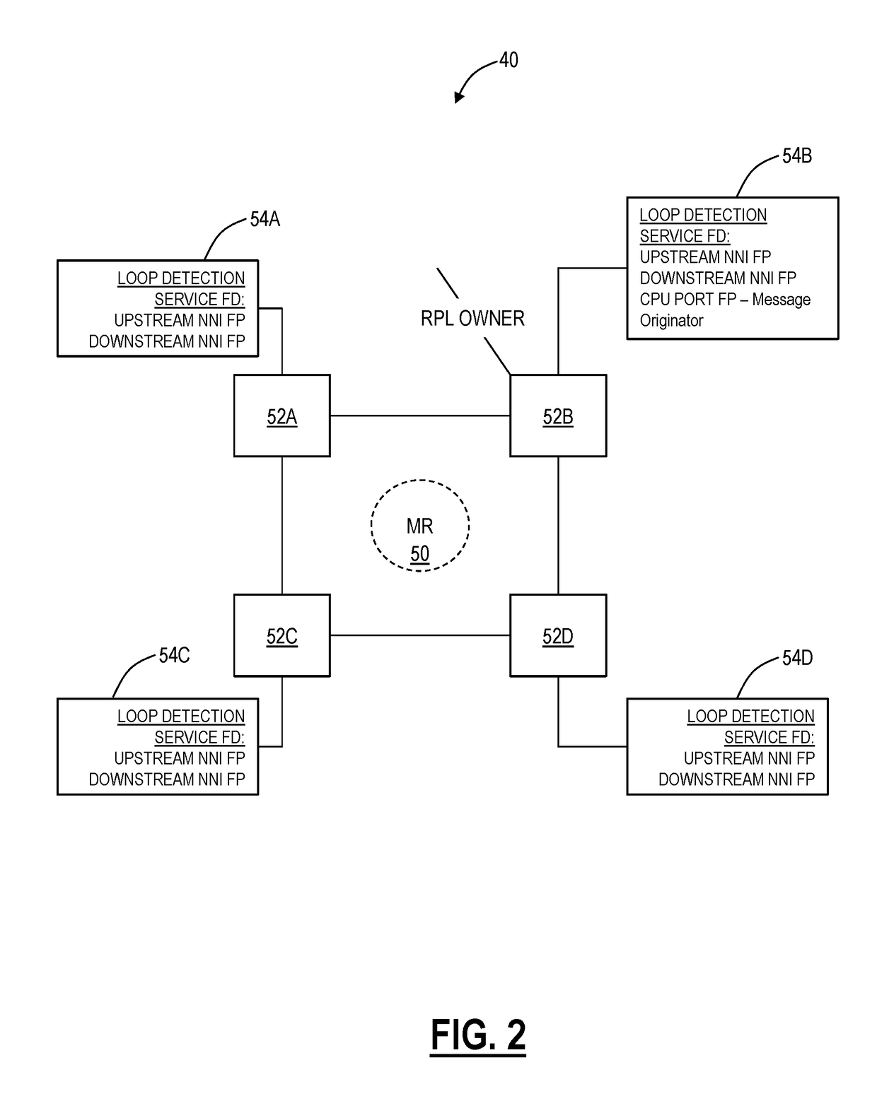
[0019]Again, in various exemplary embodiments, the present disclosure relates to systems and methods to detect and recover from a loop in an Ethernet Ring Protected network. The systems and methods provide an automatic hardware-based approach to detect quickly loops and initiate recovery. In an exemplary embodiment, the systems and methods utilize an Ethernet Virtual Local Area Network (E-VLAN) service provisioned on an Ethernet ring to detect automatically loops and cause failure recovery. The recovery can include a standard forced switch to correct a detected loop as well as providing a familiar, straightforward approach to clear automatically the detected loop using standard G.8032 processes. If the forced switch does not correct the loop, i.e., a loop is detected subsequent to the forced switch, the physical port can be disabled for all traffic to guarantee the loop is corrected. The systems and methods can include adding custom data to a forced switch APS message to provide an ...


PUM


Abstract

Loop detection systems and methods in an Ethernet Ring Protected network include, subsequent to creating a loop detection service on all nodes in the network, periodically transmitting a loop detection frame on both ports of the node; responsive to failing to receive the loop detection frame at the node, determining no loop exist in the ring; and, responsive to receiving the loop detection frame on a received port at the node, determining a loop exists in the ring and automatically implementing one or more recovery actions.

Description

FIELD OF THE DISCLOSURE[0001]The present disclosure generally relates to networking systems and methods. More particularly, the present disclosure relates to systems and methods to detect and recover from a loop in an Ethernet Ring Protected network.BACKGROUND OF THE DISCLOSURE[0002]Ethernet Ring Protection Switching, or ERPS, is described, for example, in ITU-T Recommendation G.8032 / Y.1344 (08 / 15), the contents of which are incorporated by reference. G.8032v1 supported a single ring topology and G.8032v2 supports multiple rings / ladder topology. By virtue of its topology, ring based networks, which have learning and flooding on the Layer 2 Ethernet domain, are prone to data packet loops. The G.8032 standard is based on a scheme in which loop-avoidance is the most important criterion as far as protocol specification is concerned. However, during deployment and operation, provisioning related aspects, hardware related aspects, and protocol related aspects all have the potential to cau...

Claims


Application Information

Patent Timeline
IPC IPC(8): H04L12/437H04L12/931H04L12/24H04L12/26
CPCH04L12/437H04L41/0631H04L49/354H04L43/10H04L41/0654H04L43/50
Inventor SUBRAMANIAM, BALAJINAHLOUS, PAULMITCHELL, TERRYSCHAEFER, PHIL
Owner CIENA
Learn More