
Quick connection and/or fastening system

a fastening system and fastening technology, applied in the direction of fastening means, sheet joining, mechanical equipment, etc., can solve the problems of not meeting all the needs, not being able to meet the needs of special applications, and not being able to meet the needs of all known solutions, etc., to achieve stable and safe connection, reduce size, and easy and economical manufacturing

Inactive Publication Date: 2017-06-15
BRUN GIANCARLO +1
View PDF11 Cites 0 Cited by
  • Summary
  • Abstract
  • Description
  • Claims
  • Application Information

AI Technical Summary

Benefits of technology

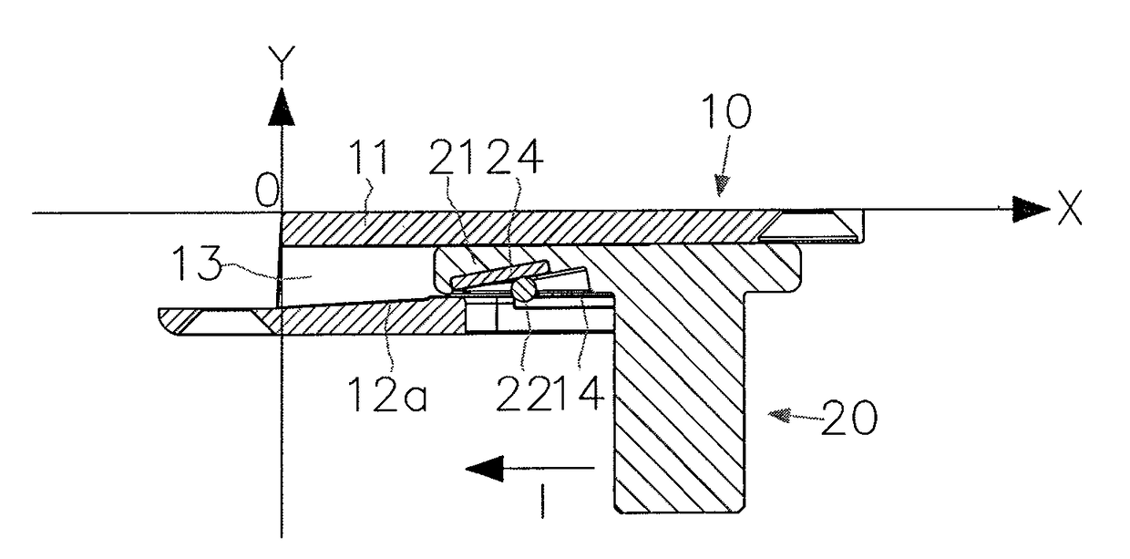
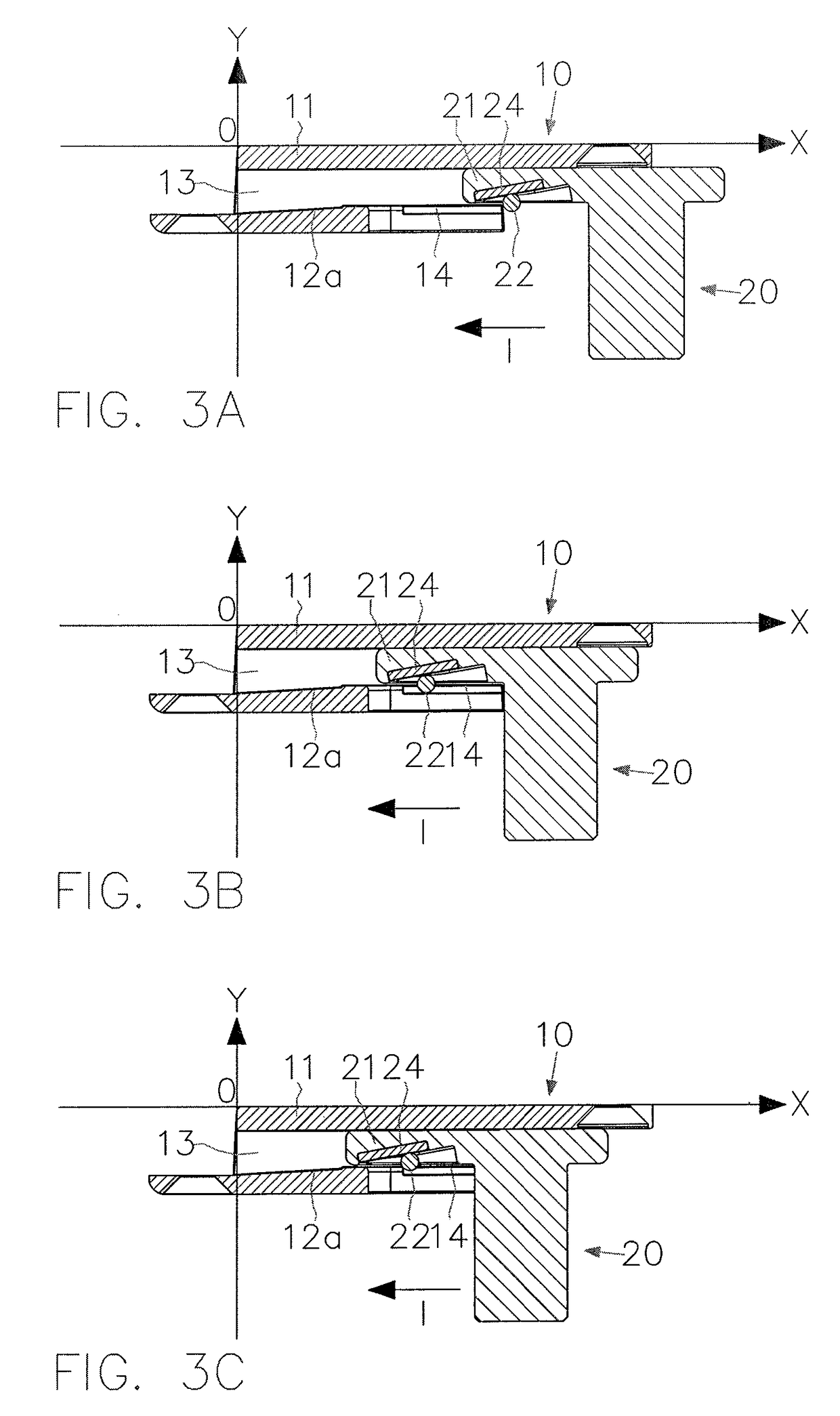
The present invention provides a quick connection and disconnection system that allows for safe and reliable connections between elements. The system includes a first and second component that can be mounted on the first and second elements, respectively, and connected or disconnected in two configurations. The first component has a rolling surface for the rolling means, while the second component has a second rolling surface for the rolling means. The rolling means counteract the translation of the terminal portion of the second component towards the disconnection configuration and can be set rotating in opposite directions to achieve the connection and disconnection configurations. The system is easy and economical to manufacture, can be used with small elements, and provides safety means to prevent accidental disconnection. The first component also has one or more grooves to house a release element to easily bring the system from the connection to disconnection configuration.

Problems solved by technology

In particular, among the typical drawbacks it should be mentioned that the coupling systems of known type, in particular the actual coupling means, do not offer the necessary reliability and the necessary guarantees against any accidental disconnection or uncoupling, so that there is the risk that during use of the finished structure this may be accidentally separated from the bearing structure, with serious risks for the user and consequent loss of stability of the structure itself.
Therefore, none of the known solutions really meets all the needs just to mentioned above.
For example, the solutions that usually offer suitable guarantees from the point of view of functionality (which cause them to be appreciated and preferred for use in the case of doors and windows for homes in general) are often characterized by considerable overall dimensions that make them unsuitable for special applications like, for example, pieces of furniture or cabinets, especially for motor homes, or in any case intended to be used in small spaces.
In the same way, the known solutions that are most suited to be used for different purposes, for example in the case of cabinets, are often characterized by a simple construction structure that reduces their overall dimensions and simplifies their assembly and use, but often goes to the detriment of reliability and functionality.

Method used


Image

  • Quick connection and/or fastening system
  • Quick connection and/or fastening system
  • Quick connection and/or fastening system

Examples


Embodiment Construction

[0038]The present invention is described here below with reference to particular embodiments, as illustrated in the attached drawings. However, the present invention is not limited to the particular embodiments illustrated in the following detailed description and represented in the figures, rather, the embodiments described herein simply exemplify the various aspects of the present invention, the scope of which is defined in the claims. Further modifications and variants of the present invention will be clear to the expert in the art.

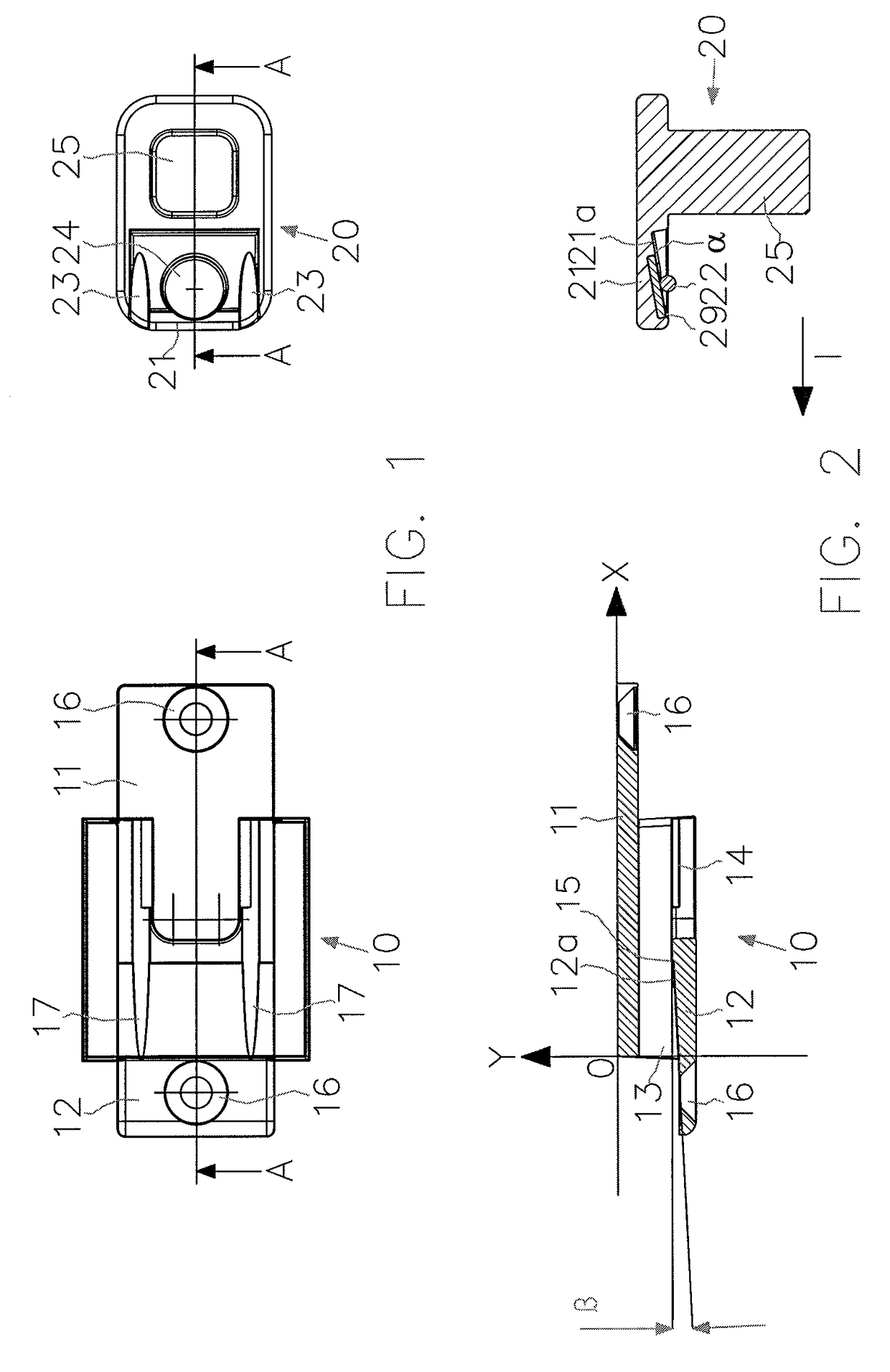
[0039]FIG. 1 schematically shows a connection and / or fastening system according to an embodiment of the present invention, in the configuration of disconnection and seen from above.

[0040]The system comprises a first component 10 (left) and a second component 20 (right). The system is suited to arrange a first element P and a second element S in a first configuration of connection and in a second configuration of disconnection. The first element P and t...


PUM


Abstract

The present invention provides a quick connection and / or fastening system suited to bring a first element (P) and a second element (S) to a first configuration of connection and to a second configuration of disconnection; the system comprising a first component (10) and a second component (20) suited to be respectively mounted on the first and on the second element (P, S), the first and the second component (10, 20) being furthermore suited to be brought to a first configuration of connection and to a second configuration of disconnection, in such a way as to alternatively allow the mutual connection and disconnection of the first and of the second element (P, S). The first component (10) is suited to house a terminal portion (21) of the second component (20) in such a way as to allow it to translate inside it. The system comprises rolling means (22). The first component (10) comprises a first rolling surface (12a) for the rolling means (22) and the terminal portion (21) of the second component (20) comprises a second rolling surface (21a) for the rolling means (22). The rolling means (22) are suited to counteract the translation of the terminal portion (21) of the second component (20) towards the configuration of disconnection of the system and are suited to be set rotating in a first direction of rotation by the translation of the terminal portion (21) of the second component (20) in order to reach the configuration of connection of the system, and suited to be set rotating in a second direction of rotation, contrary to the first direction of rotation, by the translation of the terminal portion (21) of the second component (20) in order to achieve the configuration of disconnection of the system. The system is such that the second rolling surface (21a) is configured in such a way that, in the configuration of connection, the distance between the second rolling surface (21a) and the first rolling surface (12a) increases along the direction of translation of the terminal portion (21) that leads to the configuration of disconnection of the system.

Description

TECHNICAL FIELD OF THE INVENTION[0001]The present invention concerns the field of quick connection and / or fastening systems suited to alternatively allow the connection and the disconnection of two elements. In particular, the present invention concerns the technical field of quick connection and / or fastening systems suited to alternatively allow the connection and the disconnection of two elements like, for example, the upright or the bearing structure and a shelf of a shelving system, as well as a frame, for example of a vehicle, a door, a window, a fridge, a refrigerated cabinet for supermarkets, a piece of furniture or any furnishing element, and a door leaf of the same.PRIOR ART[0002]Connection and / or coupling systems, through which two components are mutually connected to each other, are known in the art. Examples of connection systems can be found in VI 2012A000071, GB 2297793A, U.S. Pat. No. 3,896,698A and CH 600738A5. For example, in the case of the manufacture of shelving ...

Claims


Application Information

Patent Timeline
IPC IPC(8): F16B21/20F16B21/16F16B5/06
CPCF16B21/20F16B21/16F16B5/0642F16B21/165
Inventor BRUN
Owner BRUN GIANCARLO
Learn More