
Flexible image display device

a display device and flexible technology, applied in the direction of organic semiconductor devices, solid-state devices, instruments, etc., can solve the problems of low flexibility, cracks occurring, cracks in the wiring layer, etc., to minimize reduce the defect rate due to the damage of the touch panel, and excellent flexibility

Active Publication Date: 2017-05-25
DONGWOO FINE CHEM CO LTD
View PDF2 Cites 46 Cited by
  • Summary
  • Abstract
  • Description
  • Claims
  • Application Information

AI Technical Summary

Benefits of technology

The flexible image display device is designed to be very flexible and can withstand repeated bending without getting damaged. This means that the device is less likely to have defects caused by damage to the touch panel.

Problems solved by technology

The technical problem addressed in this patent text is the occurrence of cracks and driving failures in flexible image display devices caused by the wiring layer of the touch screen panel having a relatively low flexibility and being unable to stand deformation during bending of the device. Existing solutions are needed to prevent failure in the product.

Method used


Image

  • Flexible image display device
  • Flexible image display device
  • Flexible image display device

Examples


experimental example

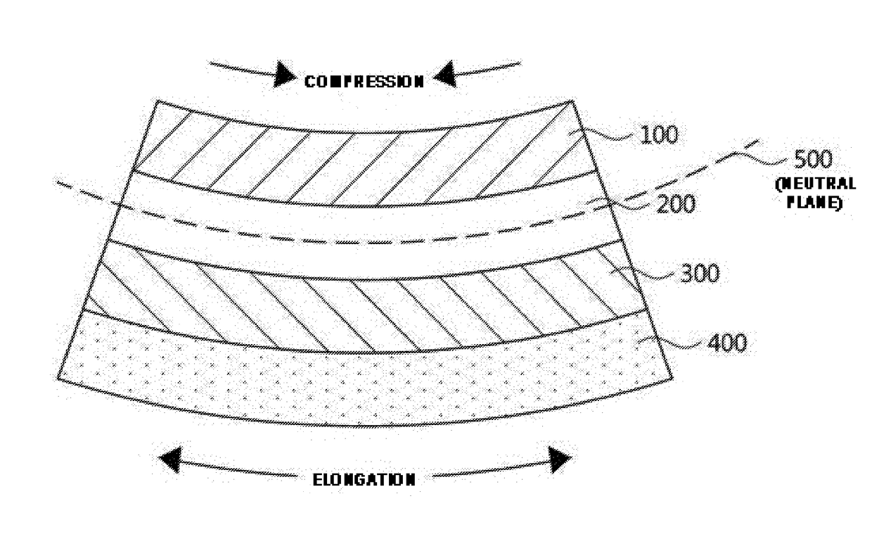
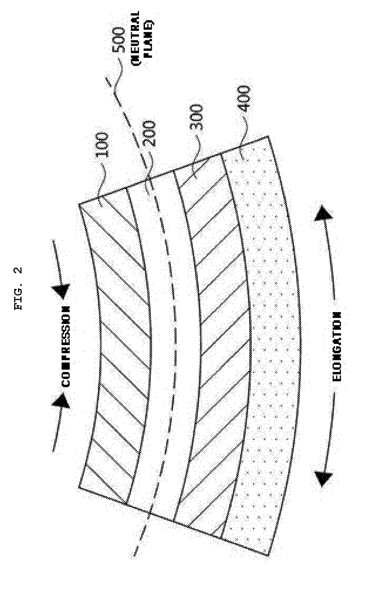
[0089](1) Calculation of Neutral Plane

[0090]A neutral plane was calculated according Equations 2 and 3 below.

σ=ER·Z[Equation2]

[0091](wherein, σ is a stress applied during bending, E is Young's Modulus, R is a radius of curvature, and Z is a neutral plane).

Z=∑i=1nEidi2+2∑i=2n(Eidi∑j=1i-1dj)2∑i=1nEidi[Equation3]

[0092](wherein, n is the number of layers, d is a thickness of individual layers, and E is Young's Modulus).

[0093](2) Assessment of Touch Properties Before Bending

[0094]A test was performed using a capacitance tester, and the touch properties before bending were determined in such a manner that, if a gap difference in numerals of an entire node is less than 20%, it is determined to be good (OK), and if the gap difference in numerals of the entire node is 20% or more, it is determined to be not good (NG).

[0095](3) Experiment for Repeated Bending Fatigue

[0096]An experiment for analysis of repeated bending fatigue was assessed using a folding tester (DLDMLH-FS, YUASA Co.) An adhes...


PUM


Abstract

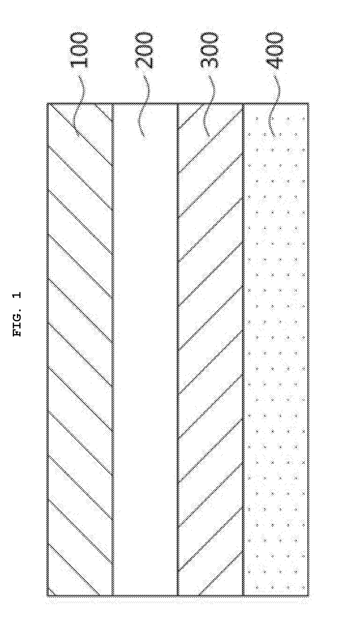
A flexible image display device includes a window substrate, a polarizing plate, and a touch panel, wherein a distance between a neutral plane and a lower surface of the touch panel based on a visible side during bending is 34% or less to an entire thickness of the flexible image display device. The flexible image display device has excellent flexibility and may significantly reduce a defect rate due to a damage of the touch panel by minimizing the damage of the touch panel even if repeatedly applying bending fatigue thereto.

Description


Claims


Application Information

Patent Timeline
Owner DONGWOO FINE CHEM CO LTD
Learn More