
Electric vehicle charging system

a charging system and electric vehicle technology, applied in the field of electric vehicles, can solve the problems of affecting the operation of the charging system, and the management of the ev charging cable (i.e. the power cable) is difficult, and the installation is surrounded by several twisted wires

Inactive Publication Date: 2017-05-11
FOURNIER PAUL W
View PDF8 Cites 28 Cited by
  • Summary
  • Abstract
  • Description
  • Claims
  • Application Information

AI Technical Summary

Benefits of technology

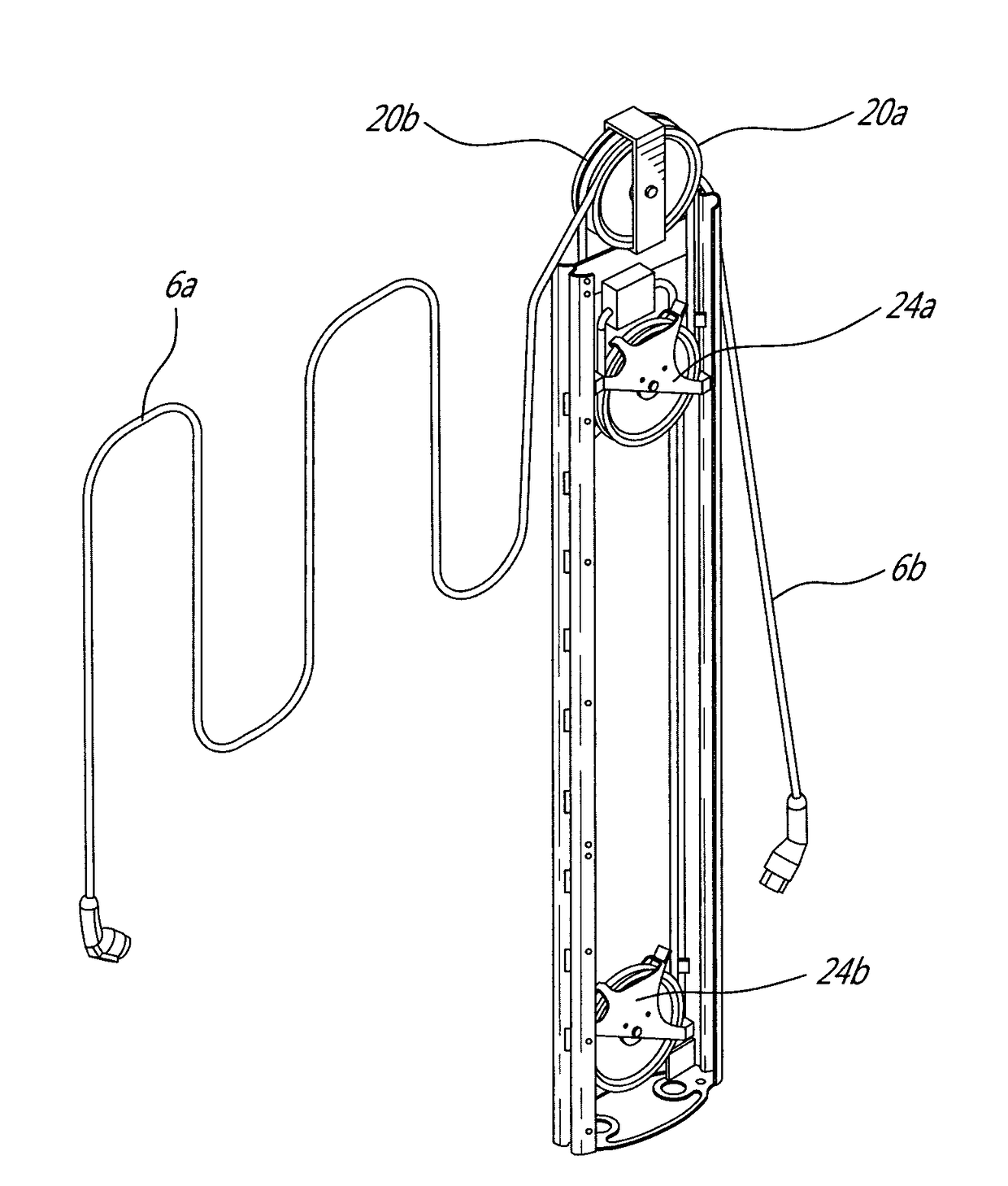
The patent is about a charging station for electric vehicles. It has an enclosure and a charging cable that can be extended and retracted. When the cable is extended, it is looped around a fixed pulley and a mobile pulley inside the enclosure. The mobile pulley can move back and forth along an axis inside the enclosure. When a certain force is applied to the free end of the charging cable, the mobile pulley moves upward against gravity, increasing the length of the charging cable. The technical effect is that it allows for easy and efficient charging of electric vehicles.

Problems solved by technology

The result is normally a bulky installation surrounded by several twisted wires, at the same time using critical space on the sidewalk and being very vulnerable to impacts from vehicles on the street and snow removal equipment on the sidewalk.
Also the management of the EV charging cables (i.e. the power cables) is challenging.
After usage, if the cables are kept loose or are not appropriately stored, the cables can become twisted along their lengths or a portion thereof may lie on the pavement where they can be easily damaged.
In Nordic countries, the cables may even become stuck in ice, thereby impeding proper access thereto.
Also, if not appropriately protected against thieves, the exposed length of cable can be easily stolen, when not in operation.

Method used


Image

  • Electric vehicle charging system
  • Electric vehicle charging system
  • Electric vehicle charging system

Examples


Embodiment Construction

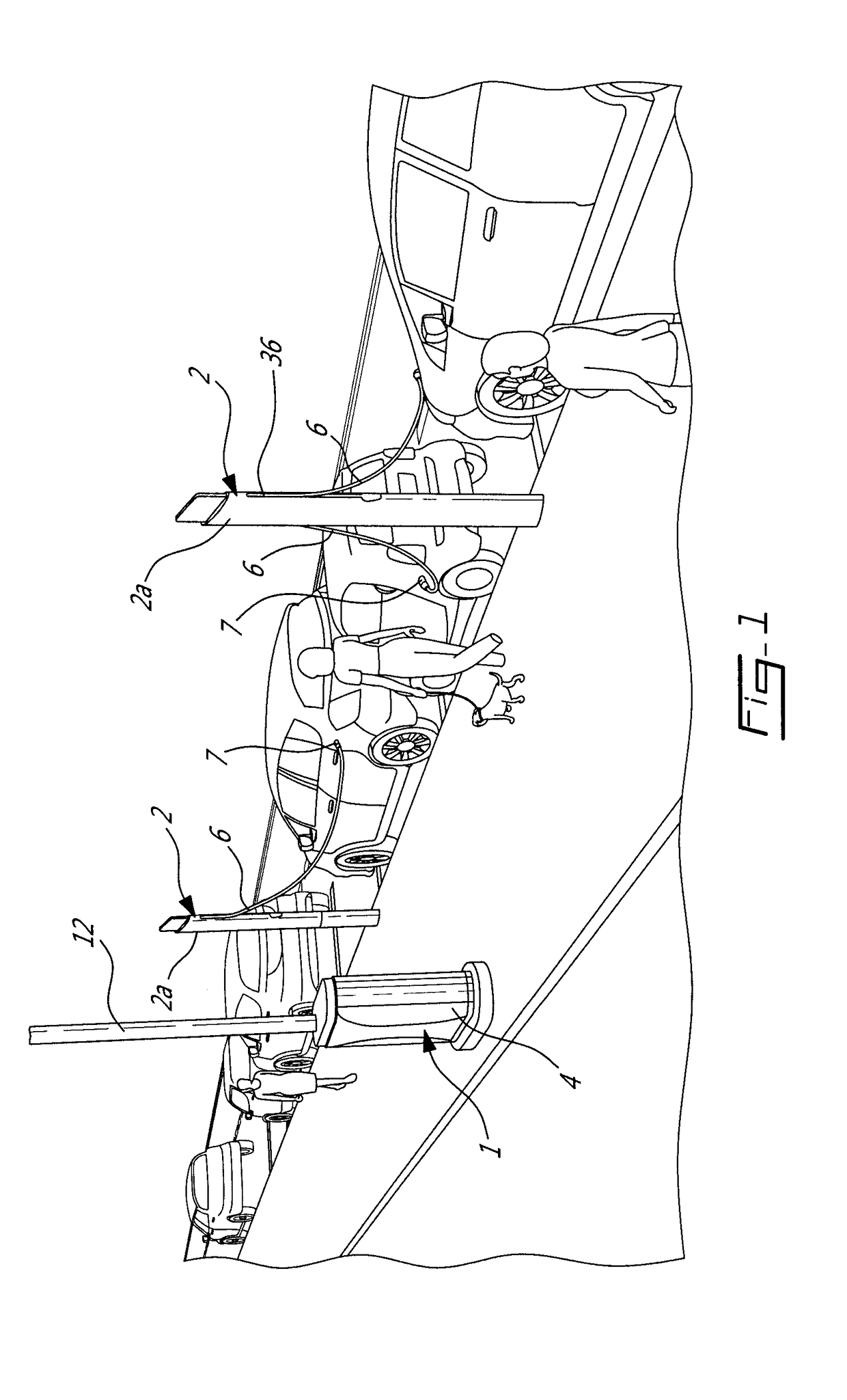
[0014]FIG. 1 illustrates one possible example of a centralized version of a EV charging system. In one aspect, this embodiment aims at removing bulky cabinets from the side of the pavement and locate it on the house side of the sidewalk, where it can be more easily installed out of the way and made less vulnerable to the various impacts. The system generally comprises a master charger unit 1 adapted to be operatively coupled to a given number of charging stations 2 (two in the illustrated embodiment). Each charging station 2 comprises an elongated upstanding enclosure 2a housing at least one power cable or EV charging cable 6 (two in the illustrated example) provided at a free end thereof with a EV charging connector 7 for connection with an EV charging socket of an EV.

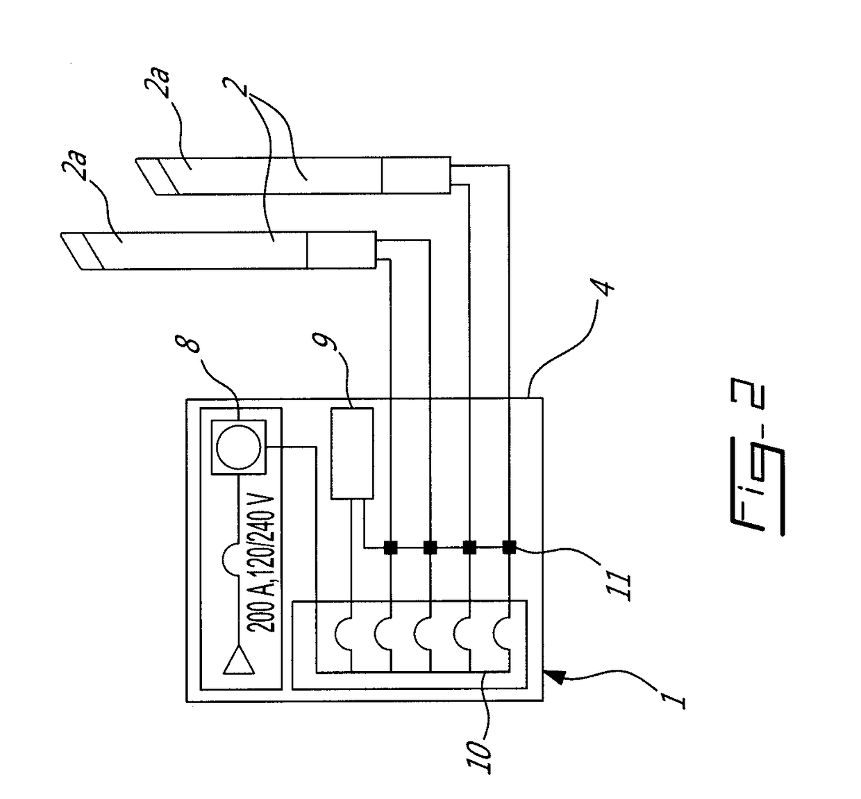
[0015]As shown in FIG. 2, the master charger unit 1 comprises a properly sized cabinet 4 housing a complete electrical entrance 8 with power and P.U. meter and a breaker panel 10, along with a charger unit and control...


PUM


Abstract

A cable management system for an electric vehicle (EV) charging station comprises an upstanding enclosure having a cable opening though which an EV charging cable can be pulled for extension. The EV charging cable is provided at a free end thereof with an EV charging connector for connection with an EV charging socket of an EV. The EV charging cable is provided at an opposed fixed end thereof with an electric connector for connection with a mating connector mounted inside the enclosure. A fixed pulley is mounted within the upstanding enclosure for rotation about a first axis normal to an upstanding axis of the enclosure. The system further comprises a mobile pulley rotatable about a second axis parallel to the first axis. The mobile pulley is vertically translatable within a guiding structure mounted inside the upstanding enclosure for movement towards and away from the fixed pulley. The fixed pulley is mounted at a higher elevation than the mobile pulley. The EV charging cable extends over the fixed pulley and the mobile pulley between its opposed free and fixed ends. The mobile pulley is moveable against gravity from a lowered position to a raised position by the application of a sufficient pulling force at the free distal end of the EV charging cable. The mobile pulley returns at least partly under gravity to its lowered position upon release of the EV charging cable, thereby automatically retracting the cable inside the upstanding enclosure.

Description

TECHNICAL FIELD[0001]The application relates generally to electric vehicles (EVs) and, more particularly, to a system for charging EVs.BACKGROUND OF THE ART[0002]As EVs become more popular, municipalities are faced with the need to deploy charging station in the public domain, namely along some of their streets to accommodate EV users whom are in frequent need for charging, namely near their home. Although it is possible to recharge EVs with wireless systems, the common art is to use chargers with direct cable connection to vehicles. We have therefore started to see chargers being installed on sidewalks along the pavement in order to be near the vehicles requiring charging. In one type of configuration, two chargers are grouped together and placed between two EV parking places in order to connect both from that location. This results into a considerably big unit fitted with long cables to reach the EV charging socket which can be located anywhere around the EV. The chargers require ...

Claims


Application Information

Patent Timeline
Patent Type & Authority Applications(United States)
IPC IPC(8): B60L11/18
CPCB60L11/1818B60L11/1825H02J7/00H02G3/0493H02G11/003Y02T10/7072Y02T90/14B60L53/16B60L53/31Y02T90/12Y02T10/70
Inventor FOURNIER, PAUL W.PLANTE, DANIEL
Owner FOURNIER PAUL W
Learn More