
System and method for assessment of a workpiece in a continuous flow process

a workpiece and continuous flow technology, applied in the direction of testing/monitoring control systems, program control, instruments, etc., can solve the problems of customer complaints, poor quality of certain pieces, and uninterrupted movement of workpieces

Active Publication Date: 2017-04-20
JOHN BEAN TECH CORP
View PDF6 Cites 15 Cited by
  • Summary
  • Abstract
  • Description
  • Claims
  • Application Information

AI Technical Summary

Benefits of technology

The patent text describes a system and method for measuring physical properties of a moving workpiece. The system includes a conveyance assembly for conveying the workpiece, a scanning assembly for scanning the workpiece, and a measurement assembly for measuring at least one physical property of the workpiece while it is in motion. The system also includes a cutting assembly for cutting portions from the workpiece, an optional unloading system operable to remove the cut portions, and a control system processor operable to process the scanning data, compare measured physical attribute data to allowed physical attribute limits, and portion specification settings to determine what use and optionally what cutting paths are required to achieve a desired product type, shape and / or size portions from the workpiece. The technical effects include improved precision and efficiency in measuring and cutting workpieces in motion.

Problems solved by technology

Processing a food product or other workpiece while it is in motion presents many challenges.
In addition thereto or in the alternative, the apparatus must process the workpiece so quickly that the motion of the workpiece is uninterrupted.
Moreover, certain pieces may be so poor in quality that they must be discarded.
This chicken product, referred to as “woody chicken,” is leading to customer complaints.
Typically these lab systems employ fixtures that have a long cycle time (e.g., about 1 minute per piece), and the fixtures destroy the workpiece during the test.
Moreover, the lab fixtures are not suitable to test the workpieces as they are moving.

Method used


Image

  • System and method for assessment of a workpiece in a continuous flow process
  • System and method for assessment of a workpiece in a continuous flow process
  • System and method for assessment of a workpiece in a continuous flow process

Examples


Embodiment Construction

[0034]The detailed description set forth below in connection with the appended drawings, where like numerals reference like elements, is intended as a description of various embodiments of the disclosed subject matter and is not intended to represent the only embodiments. Each embodiment described in this disclosure is provided merely as an example or illustration and should not be construed as preferred or advantageous over other embodiments. The illustrative examples provided herein are not intended to be exhaustive or to limit the disclosure to the precise forms disclosed. Similarly, any steps described herein may be interchangeable with other steps, or combinations of steps, in order to achieve the same or substantially similar result.

[0035]In the following description, numerous specific details are set forth in order to provide a thorough understanding of exemplary embodiments of the present disclosure. It will be apparent to one skilled in the art, however, that many embodimen...


PUM


Abstract

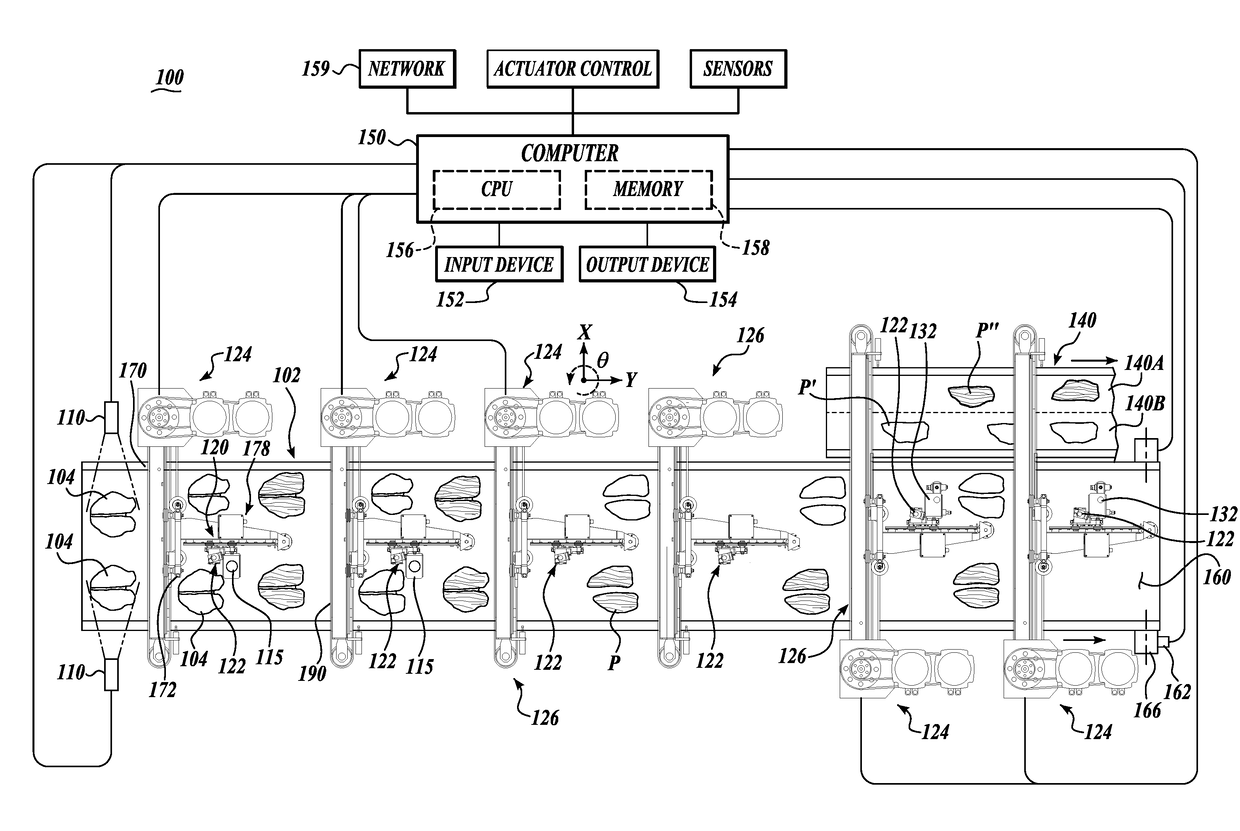
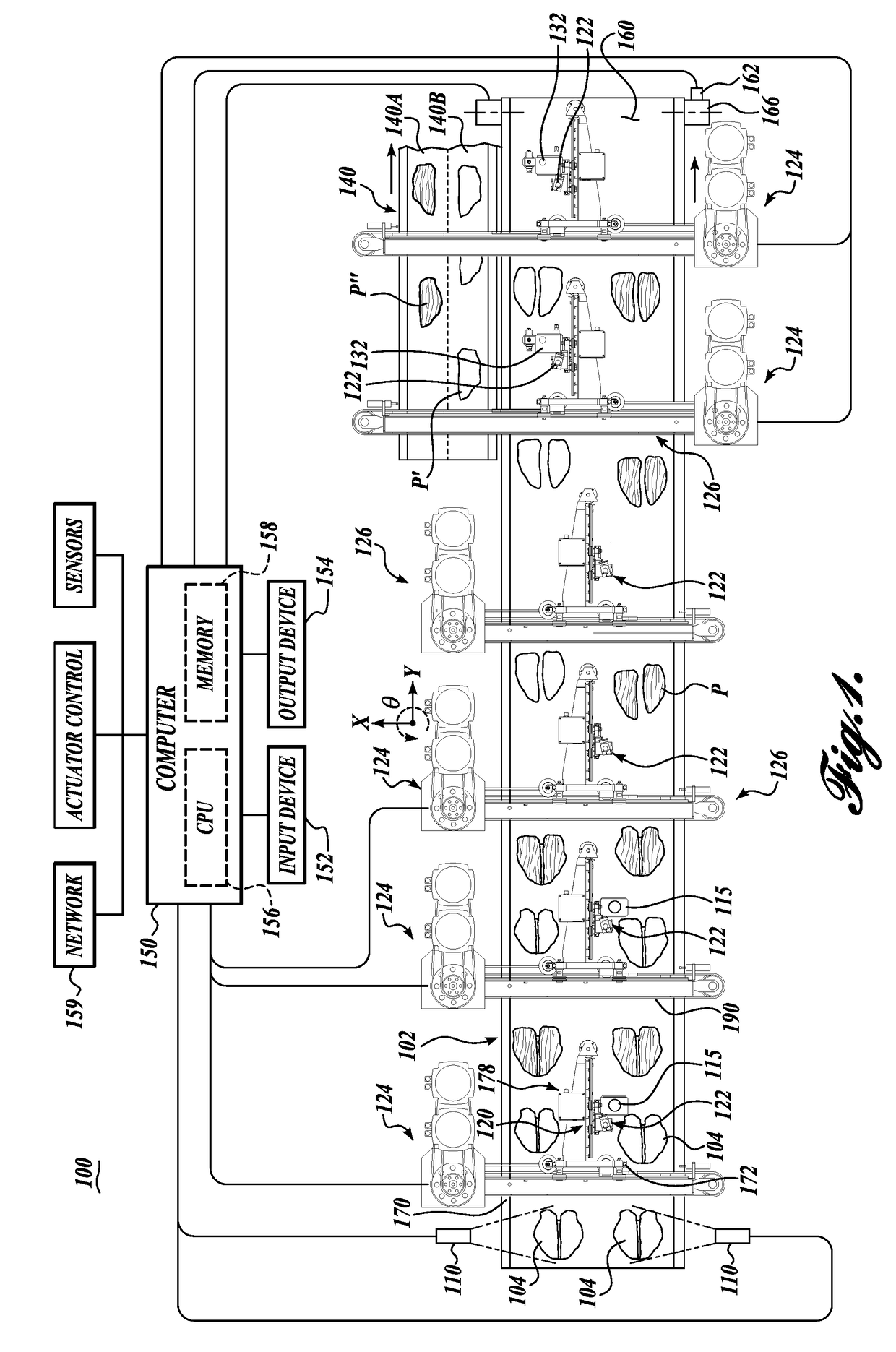
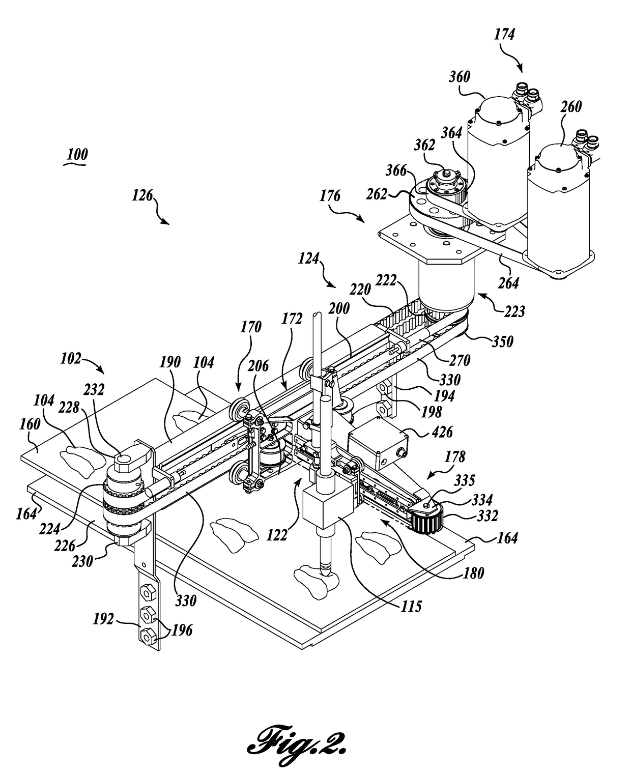
A system for measuring physical properties of a workpiece in motion which includes a conveyance assembly for conveying the workpiece, a scanning assembly for scanning the workpiece, and a measurement assembly for measuring at least one physical property of the workpiece while the workpiece is in motion.

Description

CROSS-REFERENCE TO RELATED APPLICATION[0001]This application claims the benefit of U.S. Provisional Patent Application No. 62 / 242,900, filed Oct. 16, 2015, which is incorporated herein by reference in its entirety.FIELD OF THE INVENTION[0002]The present invention relates generally to a system and method for assessing the physical properties of a workpiece in motion, and optionally processing the workpiece with a cutting assembly, and / or sorting, and / or optionally unloading the workpieces while in motion in response to measured physical properties of the workpiece.BACKGROUND OF THE INVENTION[0003]Workpieces, such food products, often vary in physical properties. The variation in physical properties may be economically significant from piece to piece. More specifically, the value and end use of a workpiece may depend in whole or in part upon the physical properties of the workpiece. In the case of a food product, tenderness, texture, stiffness, time dependent strain, resilience, or ot...

Claims


Application Information

Patent Timeline
IPC IPC(8): G05B23/02A22C21/00A22C17/00G05B19/042
CPCG05B23/0205G05B19/0428A22C21/0053G05B2219/40554A22C17/0006A22C21/0023G05B2219/31274A22C17/0086A22C17/008G01N3/42G01N33/12G01N33/34G01N3/30G01N3/40G01N33/36G01N33/44G01N33/46G01N2203/0094
Inventor HOCKER, JON A.BLAINE, GEORGE R.PFARR, CRAIG E.
Owner JOHN BEAN TECH CORP
Learn More