Modular Block And Electronic Block System

a module block and electronic block technology, applied in the field of electronic blocks, can solve the problems of low interest, poor flexibility, undetachable integrity of common circuit boards or functional devices, etc., and achieve the effects of improving the development of more functions, reducing the placement requirements to the pole, and expanding the use of data signal lines

Inactive Publication Date: 2017-04-20
SHENZHENSHI HANTONG TECH CO LTD
View PDF3 Cites 4 Cited by
  • Summary
  • Abstract
  • Description
  • Claims
  • Application Information

AI Technical Summary

Benefits of technology

The patent text describes a connector that has a main body and a detachable rear cover made of insulating material. The connector has an attraction element inside it, which can be a magnet or a magnetically attractive metal. This attraction element helps to protect and prolong the service life of the connector. The connector can also have one or more magnets inside it, which helps to lower the manufacture costs and makes it easier to place the magnets in the correct position. This placement of the magnets does not occupy the surface of the main body, allowing for more conductive terminals to be added and ensuring that the magnet is well protected. Overall, this invention allows for the efficient and cost-effective production of connectors with magnets.

Problems solved by technology

However, a common circuit board or functional device is an undetachable integrity.
Such a product is limited to a few single functions and thus has poor flexibility.
For a user who likes to manually detach or splice a toy, he / she cannot learn the structures and functions of various functional modules in this product and thus it is of a low interesting.
However, this disclosed technique has the following problems during practical application.
1. It is limited to three groups of lines on the circuit board and the connector, which limits the expansive usage of the data signal lines and also the development of more functions of the electronic block system.
2. Arrangement of the magnet has an applicability problem.
First, the multi-magnet design has high requirements on the placement of the pole thereof, which is not beneficial for the reduction of manufacture costs; it directly occupies a large portion of the coupling surface of the insulating body and thus is not beneficial for the expansion of more conductive connectors.
It is more important that the magnet is directly exposed on the coupling surface, which hampers the protection to the magnet.
The magnet will be easily oxidized after long-time hand contact and collision and will produce magnet power debris due to the exposure.
In the meantime, the magnet will gradually lose efficacy and the magnet attraction force will be reduced due to magnet debris, and even the magnet will be damaged.
This limitation can achieve relevant functions but its “side by side arrangement” will cause high requirements on space and thus the expansion of more conductive connectors is restricted seriously.
It is also not easy to be processed during manufacturing and the costs are high.

Method used


Image

  • Modular Block And Electronic Block System
  • Modular Block And Electronic Block System
  • Modular Block And Electronic Block System

Examples


embodiment 1

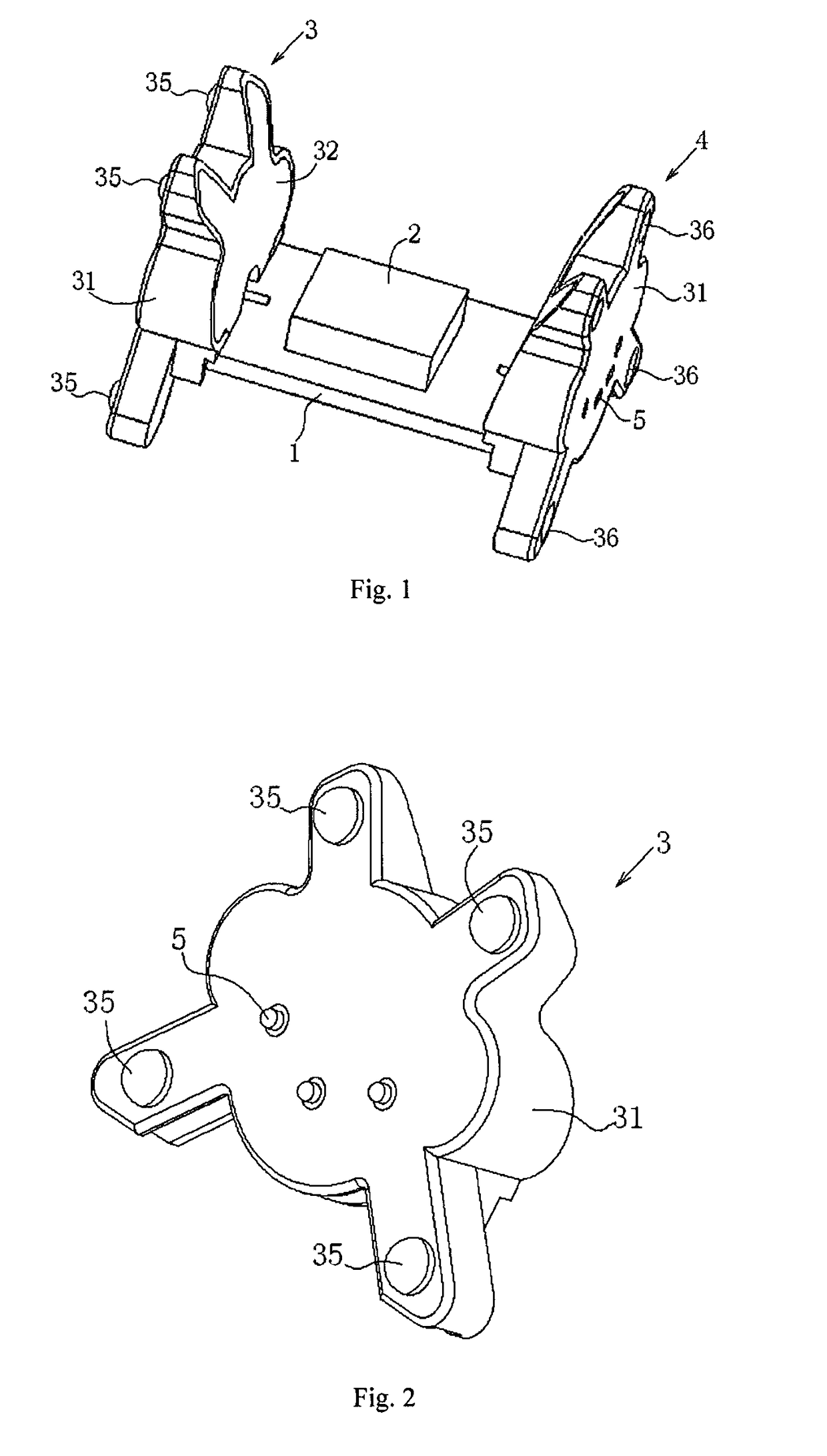
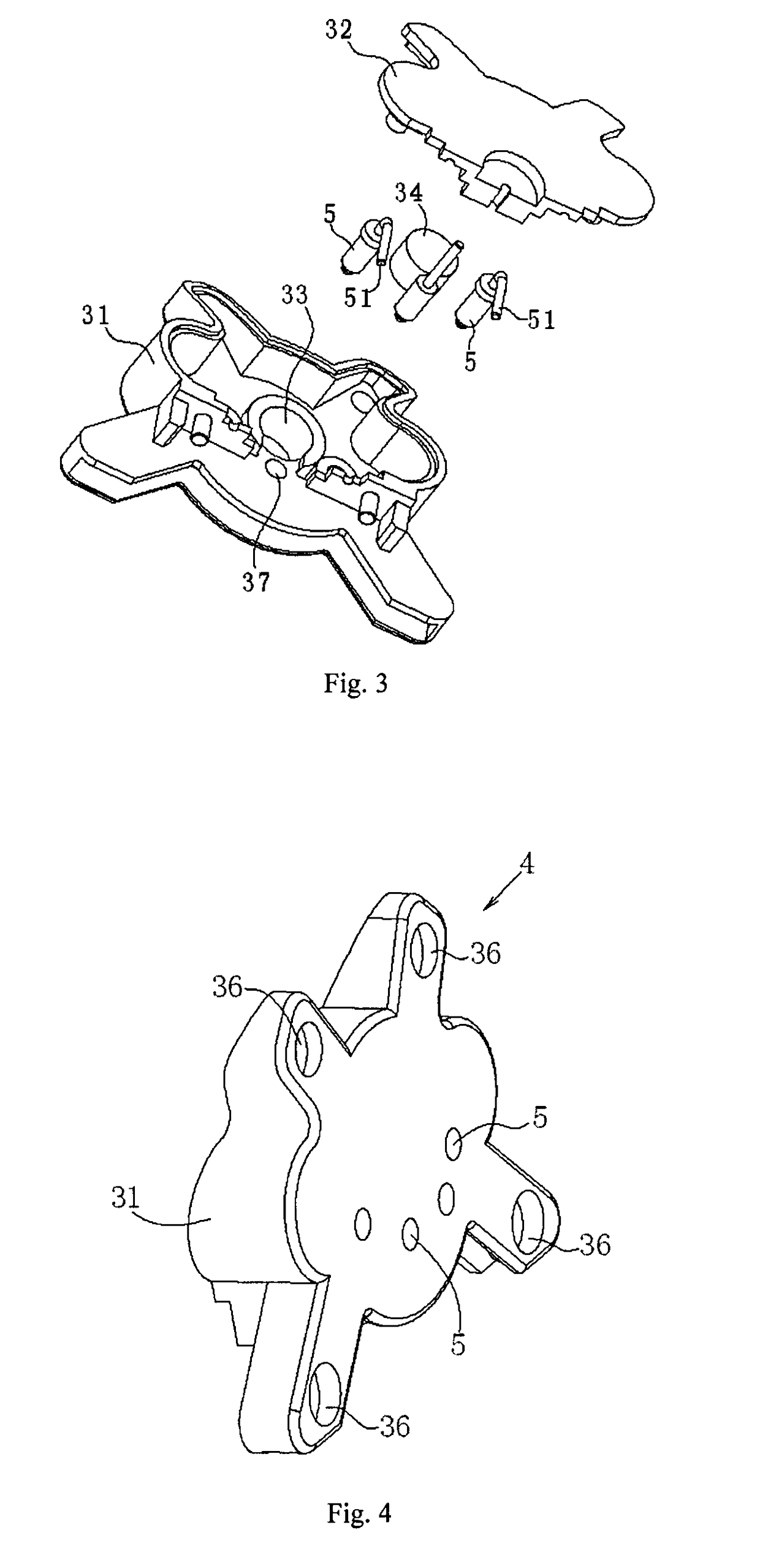
[0027]As shown in FIG. 1, the modular block in this embodiment comprises a circuit board 1 and a functional circuit 2 disposed on the circuit board 1. An input connector 3 and an output connector 4 are connected to the circuit board 1. The input connector 3 and the output connector 4 are both provided with a plurality of conductive terminals 5 connected to the circuit board 1. The plurality of conductive terminals 5 are a positive power conductive terminal, a negative power conductive terminal and a data signal conductive terminal, respectively.

[0028]As shown in FIGS. 2 to 5, the input connector 3 and the output connector 4 both comprise a main body 31 and a rear cover 32. The rear cover 32 is detachably mounted on the main body 31. The main body 31 and the rear cover 32 are both made of an insulating material, in particular, a plastic material. The main body 31 or the rear cover 32 has a cavity 33. An attraction element 34 is provided in the cavity 33. The attraction element 34 is ...

embodiment 2

[0036]The modular block in this embodiment is substantially the same as that in embodiment 1. Their differences lie in that the circuit board 1 of the modular block in this embodiment is connected to one input connector 3 and a plurality of output connectors 4 and the functional circuit 2 has the function of power source and signal conduction.

embodiment 3

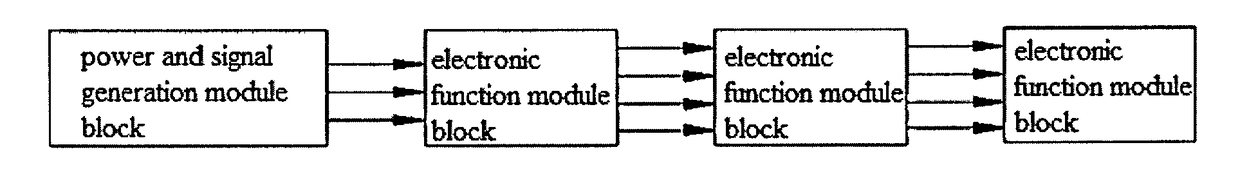
[0037]As shown in FIG. 6, the electronic block system in this embodiment comprises a power and signal generation module block and a plurality of the modular blocks. The plurality of modular blocks cascade with the power and signal generation module block.

[0038]In the present invention, cascading means that the modular blocks are electrically connected to the power and signal generation module block for current delivery and signal transmission.

[0039]The power and signal generation module block has a power circuit and a signal source circuit which are electrically connected to the input connector 3 of the modular block.

[0040]The functional circuit 2 of the modular block is a function execution device. The modular block in embodiment 1 may be adopted. The function execution device can be selected according to user's demand, such as LED light, beeper, loudspeaker, vibrator, motor, switch, display screen, etc. The input connector 3 and the output connector 4 of the modular block can be p...


PUM


Abstract

A modular block, including a circuit board, a functional circuit disposed on the circuit board, an input connector and an output connector. The input connector and the output connector are both provided with a plurality of conductive terminals connected to the circuit board. The plurality of conductive terminals are a positive power conductive terminal, a negative power conductive terminal and a data signal conductive terminal respectively. At least one of the input connector and the output connector is provided with a plurality of the data signal conductive terminals. Also provided is an electronic block system. The input connector and the output connector of the modular block can be provided with one or more data signal conductive terminals according to actual needs, data signal lines can be expanded for use, and the modular block has more functions and applications.

Description

FIELD OF THE INVENTION[0001]The present invention relates to an electronic block, and more particularly to a modular block and an electronic block system applied to teaching of experiments and electronic block toys.BACKGROUND OF THE INVENTION[0002]It is known that a traditional electronic block system for teaching of experiments or electronic block toys usually includes a complete circuit board and various functional devices. Designated lines and installation holes are provided on the circuit board. In use, the required functional devices are installed on the circuit board to achieve specific functions. However, a common circuit board or functional device is an undetachable integrity. Such a product is limited to a few single functions and thus has poor flexibility. For a user who likes to manually detach or splice a toy, he / she cannot learn the structures and functions of various functional modules in this product and thus it is of a low interesting.[0003]Chinese patent CN203108212...

Claims


Application Information

Patent Timeline
Patent Type & Authority Applications(United States)
IPC IPC(8): A63H33/04A63H33/10A63H33/26
CPCA63H33/042A63H33/10A63H33/046A63H33/26
Inventor WEI, ZHENGPENG
Owner SHENZHENSHI HANTONG TECH CO LTD
Why Eureka
Try Eureka