Curved display panel and display apparatus containing the same
a display panel and display panel technology, applied in non-linear optics, instruments, optics, etc., can solve the problems of severe light leakage in the edge region of the display panel, the optical axes of the two substrates often deviating from each other, etc., to reduce the dark state light leakage and reduce the first curvature
- Summary
- Abstract
- Description
- Claims
- Application Information
AI Technical Summary
Benefits of technology
Problems solved by technology
Method used
Image
Examples
embodiment 1
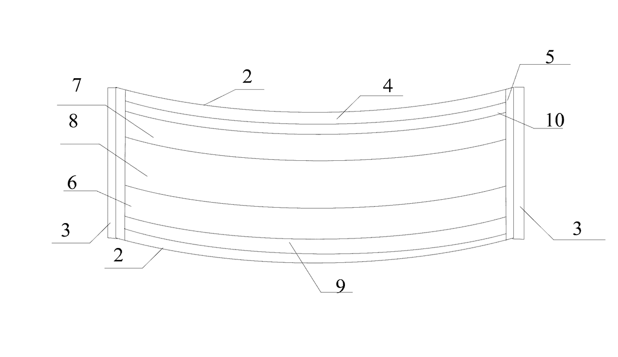
[0029]The present disclosure provides a curved display panel. As shown in FIGS. 1 to 6, the curved display panel 1 may be provided. Specifically, as shown in FIG. 1, the curved display panel 1 may include an array substrate 6 and a color filter substrate 7 bonded to each other. A liquid crystal layer 8 may be bonded or formed between the array substrate 6 and the color filter substrate 7.
[0030]On the two sides of the bonded array substrate 6 and the color filter substrate 7 facing away from the liquid crystal layer 8, a first polarizer 9 and a second polarizer 10 may be placed. One of the first polarizer 9 and the second polarizer 10 may be arranged on one side and the other one of the first polarizer 9 and the second polarizer 10 may be arranged on the other side. The light polarization direction of the first polarizer 9 and the light polarization direction of the second polarizer 10 may be perpendicular to each other.
[0031]The array substrate 6 and the color filter substrate 7 may...
experiment two
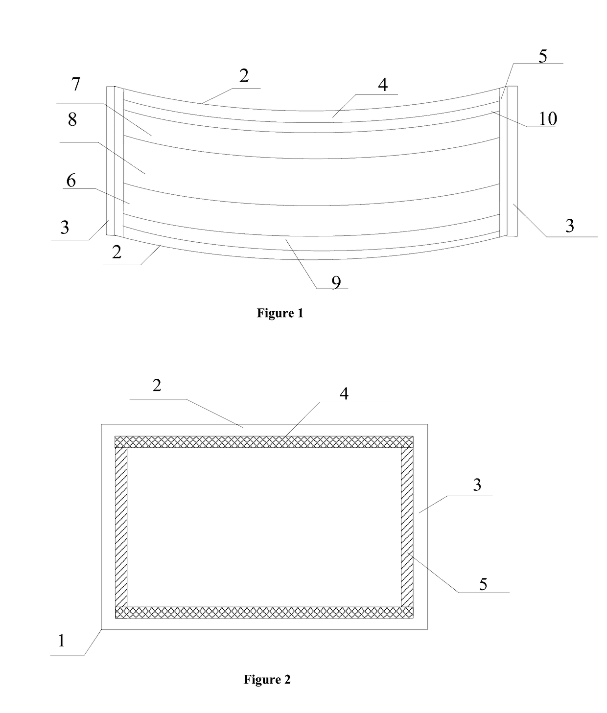
[0059]As shown in FIG. 2, the second sealant 5, with a Young's modulus of 1.6 Gpa, may be used to seal the second side regions 3 of the curved display panel 1. The first sealant 4, with a Young's modulus of 0.16 Gpa, may be used to seal the first side regions 2 of the curved display panel 1. Other parameters may be the same as in embodiment 1.
[0060]Other conditions or parameters may include the follows. The curved display panel may be an 18.5″ ADS curved display panel 1. The optical phase retardation of the liquid crystal layer 8 may be about Δnd=348 nm. The effective display area may be about 410×230 mm. The sealant may each have a width of about 1 mm. The substrate may each have a thickness of about 0.5 mm. The radius of curvature of the substrates may be about 2000 mm.
[0061]The four side regions in FIG. 5 may correspond to the first side regions 2 and the second side regions 3 of the curved display panel 1. The lengths of the four side regions in FIG. 5 may be proportional to the...
experiment three
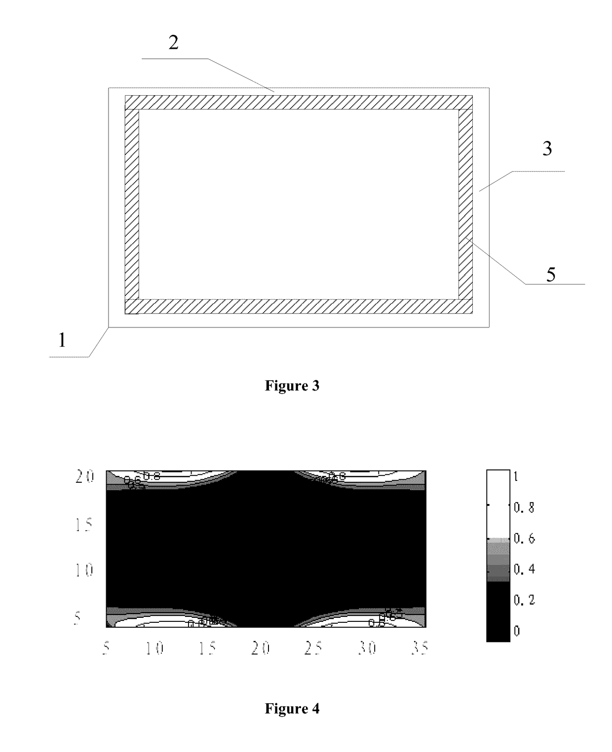
[0064]As shown in FIG. 6, the second sealant 5, with a Young's modulus of 1.6 Gpa, may be used to seal the second side regions 3 of the curved display panel 1. The first sealant 4, with a Young's modulus of 0.016 Gpa, may be used to seal the first side regions 2 of the curved display panel 1. Other parameters may be the same as in embodiment 1.
[0065]Other conditions or parameters may include the follows. The curved display panel may be an 18.5″ ADS curved display panel 1. The optical phase retardation of the liquid crystal layer 8 may be about Δnd=348 nm. The effective display area may be about 410×230 mm. The sealant may each have a width of about 1 mm. The substrate may each have a thickness of about 0.5 mm. The radius of curvature of the substrates may be about 2000 mm.
[0066]The four side regions in FIG. 6 may correspond to the first side regions 2 and the second side regions 3 of the curved display panel 1. The lengths of the four side regions in FIG. 6 may be proportional to th...
PUM
| Property | Measurement | Unit |
|---|---|---|
| width | aaaaa | aaaaa |
| thickness | aaaaa | aaaaa |
| brightness | aaaaa | aaaaa |
Abstract
Description
Claims
Application Information
 - R&D
- Intellectual Property
- Life Sciences
- Materials
- Tech Scout
- Unparalleled Data Quality
- Higher Quality Content
- 60% Fewer Hallucinations
Browse by: Latest US Patents, China's latest patents, Technical Efficacy Thesaurus, Application Domain, Technology Topic, Popular Technical Reports.
© 2025 PatSnap. All rights reserved.Legal|Privacy policy|Modern Slavery Act Transparency Statement|Sitemap|About US| Contact US: help@patsnap.com


