
Self-tuning system for manipulating complex fluids using electrokinectics

a technology of complex fluids and self-tuning, applied in fluid controllers, circuit elements, laboratory glassware, etc., can solve the problems of inflexibility, prone to failure, and inability to perform multiple applications,

Active Publication Date: 2017-04-13
IBM CORP
View PDF10 Cites 8 Cited by
  • Summary
  • Abstract
  • Description
  • Claims
  • Application Information

AI Technical Summary

Benefits of technology

This patent describes a system for manipulating electric fields in a microscopic fluid channel to control the flow of particles, such as cells, in real-time. The system includes an electric field producer that applies a non-uniform and adjustable electric field to the fluid channel using a controllable electric field. The system also includes sensors to measure various parameters of the fluid flow, such as size, chemical composition, and flow speed, and a controller to adjust the electric field based on the sensor signals. The system can be used to separate, trap, steer, and manipulate different types of particles within the fluid. The technical effects of this patent include the ability to control the flow of particles in a microscopic fluid channel, which can be useful in various applications such as separation, trapping, and manipulation of particles for research and applications.

Problems solved by technology

This makes the device simpler to manufacture but less flexible.
Such simple designs can be very sensitive to variability introduced during the manufacturing processes and can be prone to failure when this variability is significant.
As such, the electrode design is highly application specific and it can only serve the original design purpose, with no flexibility to perform multiple applications.
Solutions based only on simulations are limited by the fidelity of models and by the knowledge of the boundary conditions and physical parameters, such as temperature, viscosity, flow speed, etc.
None of these solutions can prescribe a real-time optimization of field landscapes in an automated fashion.
Such a device cannot be altered at a later time and will only be able to manipulate the very set of particles for which was designed.
Moreover, such electrodes commonly have crudely designed layouts comprising simple shapes and of dimensions that are often only manually adjusted through trial and error to achieve the desired effects.
Such simple designs can be very sensitive to variability introduced during the manufacturing processes and can be prone to failure when this variability is significant.
Solutions based on the deposition of a 2D array of electrodes do not combine the effects of the electric field and a flowing fluid on the particle movement and are limited to slow, incremental movements by switching on and off adjacent electrodes one by one.
This method can thus only handle a few particles that are nearly stationary, with very low throughput and is difficult to automate.
Eventual washing steps can also be challenging to perform under this technique.
Solutions based on highly focused laser beams lack the portability, low-cost and ease-of-use that is desired for such devices.
These devices use one or more laser beams, an intricate optical setup and much more power to run than do previous solutions.
These solutions have not been built to be optimized for given operational parameters or to be tuned and controlled in real time.
However, none of the current solutions prescribes a dynamic or real-time optimization or control method for the electric field landscapes used to manipulate particles flowing in fluid in an automated fashion.

Method used


Image

  • Self-tuning system for manipulating complex fluids using electrokinectics
  • Self-tuning system for manipulating complex fluids using electrokinectics
  • Self-tuning system for manipulating complex fluids using electrokinectics

Examples


Embodiment Construction

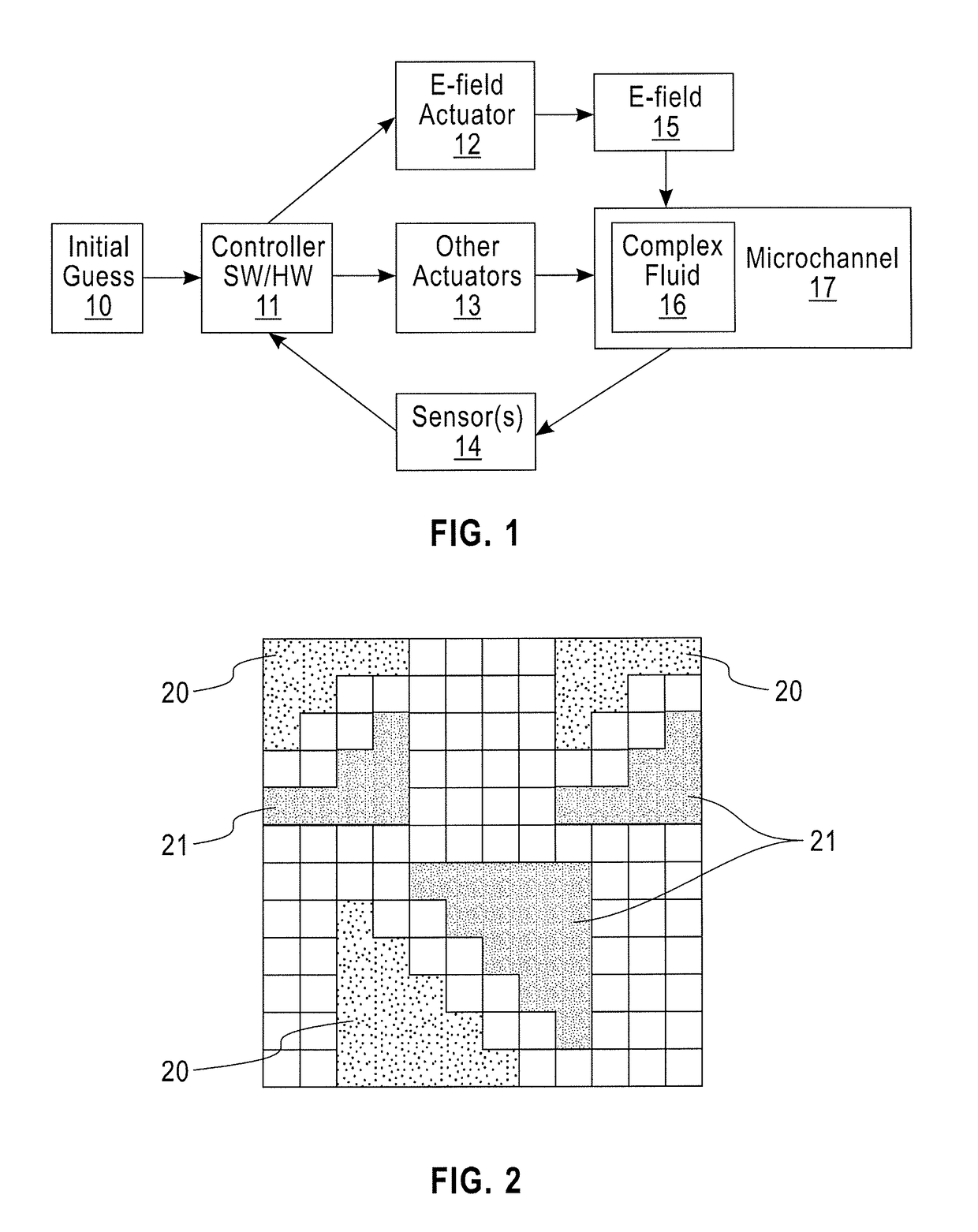
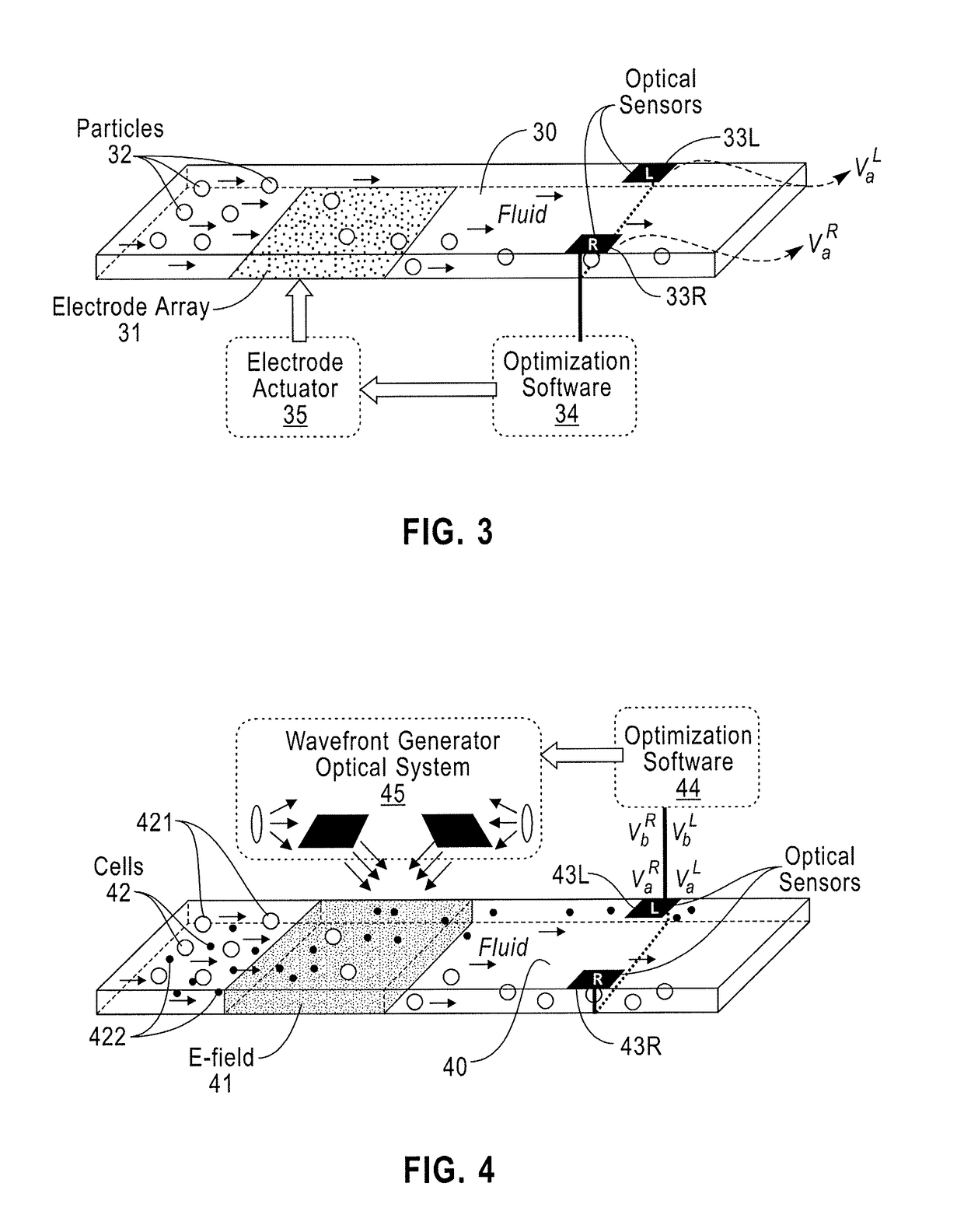
[0050]Exemplary embodiments of the disclosure can provide a system for actively controlling or for optimizing in real time the electrical field landscape by using real data in an automated fashion. Embodiments of the disclosure can provide a method that allows for the automatic optimization of an electric field distribution based on data collected in real-time to manipulate particles / cells / droplets as they are carried by fluid flowing in a microchannel. Accordingly, while the disclosure is susceptible to various modifications and alternative forms, specific embodiments thereof are shown by way of example in the drawings and will herein be described in detail. It should be understood, however, that there is no intent to limit the disclosure to the particular forms disclosed, but on the contrary, the disclosure is to cover all modifications, equivalents, and alternatives falling within the spirit and scope of the disclosure.

[0051]A single device according to an embodiment of the discl...


PUM


Abstract

A system for manipulating electric fields within a microscopic fluid channel includes a fluid channel with an inlet and an outlet to support fluid flow, at least one controllable electric field producer that applies a non-uniform and adjustable electric field to one or more regions of the fluid channel, one or more sensors that measure one or more parameters of a fluid flowing through the fluid channel, and a controller with hardware and software components that receives signals from the one or more sensors representative of values of the one or more parameters and, based on the parameter values, drives one or more actuators to adjust the electric field produced by the plurality of electric field producers. A complex fluid including at least two components flows through the fluid channel, where at least one of the at least two components comprises

Description

BACKGROUND[0001]1. Technical Field[0002]Embodiments of the present disclosure are directed to the manipulation of complex fluids, or one of its constituents, flowing through microchannels via the optimization of electric field landscapes capable of applying electrokinetic forces.[0003]2. Discussion of the Related Art[0004]Because of their potential as miniaturized laboratory platforms capable of performing entire biological and chemical experiments on small, inexpensive chips, there has been a rapid increase in research and development of microfluidics-based devices used for Point of Care (PoC), Lab on a Chip (LoaC), and immunoassays applications. Microfluidic devices can enable touchless manipulation of single cells, microorganisms, droplets or particles through the exploitation of electro-hydrodynamic effects, also known as electrokinetics, only noticeable at micro-scales. In particular, one such effect is known as dielectrophoresis.[0005]A dielectrophoretic (DEP) force arises fro...

Claims


Application Information

Patent Timeline
IPC IPC(8): F15C1/04
CPCF15C1/04B01L2300/0645B01L3/502761B01L2200/0652B01L2400/0424B01L2200/143B01L2200/147B01L2300/0663
Inventor AZPIROZ, JAIONE TIRAPUBRYANT, PETER WILLIAMGIRO, RONALDOBARROS FERREIRA, RODRIGO NEUMANNOHTA, RICARDOS LUIS
Owner IBM CORP
Learn More