
Flying apparatus with multiple sensors and gesture-based operation

Inactive Publication Date: 2017-04-13
LEE HOI HUNG HERBERT
View PDF0 Cites 20 Cited by
  • Summary
  • Abstract
  • Description
  • Claims
  • Application Information

AI Technical Summary

Benefits of technology

The invention provides apparatuses and methods for an unmanned flying craft that can sense and adjust its flying patterns based on its surroundings. It uses sensors to detect hand gestures, automatically control altitude, and detect obstacles. The flying object has a main body, flying arms, and blade with a rotor and height sensor. It also has a charger adapter and controller to coordinate the sensors. The bottom of the main body has an adapter for connecting accessories like a camera, and the flying object may have a second flying arm that extends perpendicular to the first flying arm. A camera may also be attached to the flying object via a sliding structure that can move it along the main body, flying arms, or other areas. Overall, the invention allows for more intuitive and autonomous flying of unmanned craft.

Problems solved by technology

Flying toys, regardless of whether they are planes, helicopters, or quadcopters, are not easy to maneuver, especially for children and beginners.
A problem with current designs for these kinds of smaller, hovering remote-control flying craft is that the competing design considerations of weight, cost and performance have resulted in a very limited set of designs for how these craft are constructed.
Running the rotors into an obstacle, like a ceiling when flying indoors, almost always causes the craft to crash and potentially suffer damage as a result.
These existing designs for smaller, hovering remote-control flying craft suffer from various problems, including cost of manufacture, ease of operation, accuracy of navigation, durability, and safety during operation, among others problems.
However, wireless gesture control, proximity sensing technologies, and altitude control capability are yet to be successfully implemented into remote flying craft.

Method used


Image

  • Flying apparatus with multiple sensors and gesture-based operation
  • Flying apparatus with multiple sensors and gesture-based operation
  • Flying apparatus with multiple sensors and gesture-based operation

Examples


Embodiment Construction

[0022]References will now be made in detail to the present exemplary embodiments, examples of which are illustrated in the accompanying drawings. Certain examples are shown in the above-identified figures and described in detail below. In describing these examples, like or identical reference numbers are used to identify common or similar elements. The figures are not necessarily to scale and certain features and certain views of the figures may be shown exaggerated in scale or in schematic for clarity and / or conciseness.

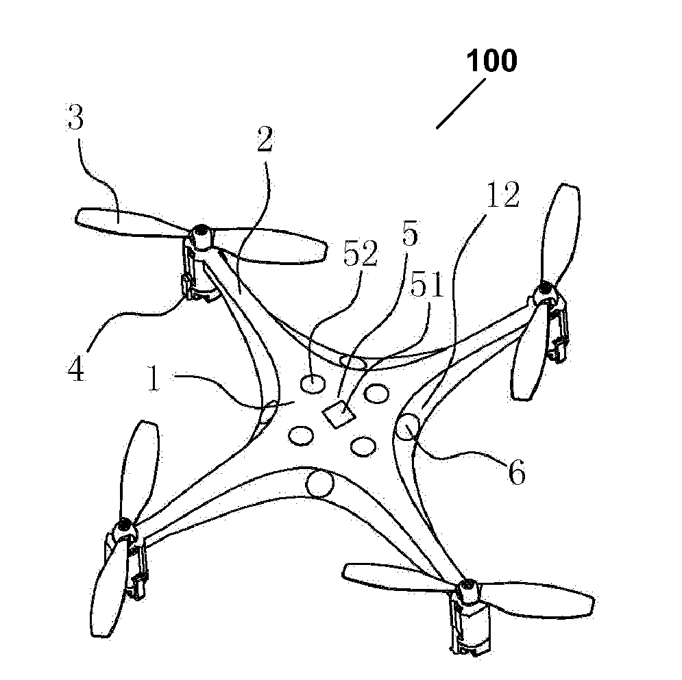
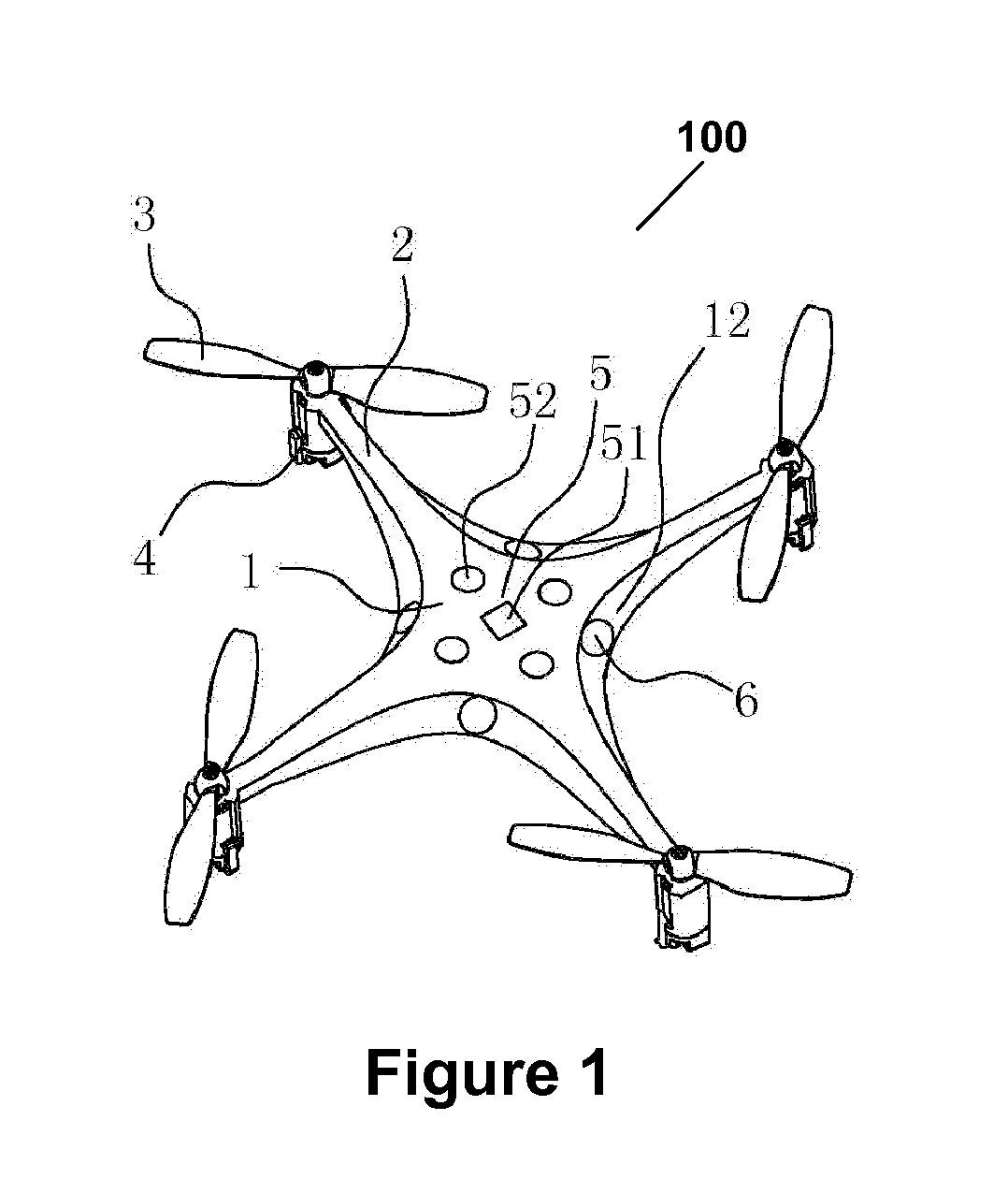
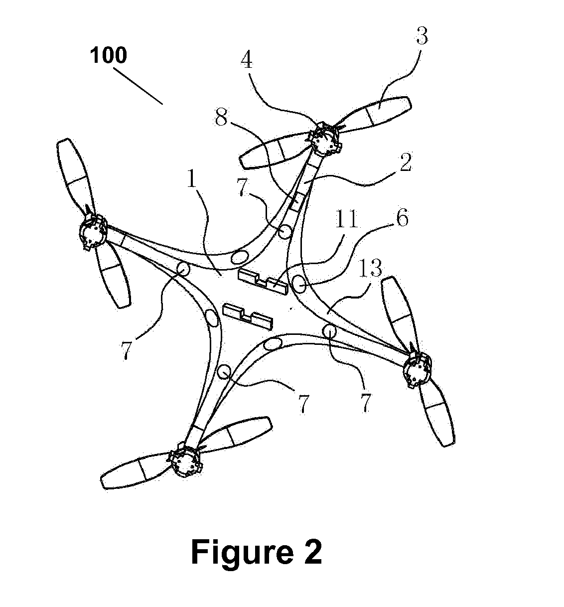
[0023]Referring now to FIG. 1, a flying object is depicted according to an embodiment of the disclosed technology. The terms “flying object” and / or “unmanned aerial vehicle,” (“UAV”) as used in this disclosure, refer to any autonomous or semi-autonomous vehicle that is capable of performing some functions without a physically-present human pilot. The terms “flying object”, “flying apparatus” and / or “unmanned aerial vehicle” may be used interchangeably throughout thi...


PUM


Abstract

According to embodiments of the disclosed technology, apparatuses and methods are provided for an unmanned flying craft that senses different aspects of its surroundings and adjusts flying patterns in response thereto. The apparatus may employ a plurality of sensors for detecting and receiving information and / or signals from locations surrounding the apparatus. The disclosed technology may employ sensors directed to receiving and translating hand gesture signals performed by a user. Moreover, other sensors may constantly monitor elevation and automatically control altitude based on elevation. Still further, proximity sensors may sense nearby obstacles to be avoided by the flying craft.

Description

FIELD OF THE INVENTION[0001]The present invention generally relates to flying apparatuses and more particularly to a flying apparatuses with one or more sensors for improving performance and reducing risk of damage.BACKGROUND OF THE INVENTION[0002]Remote-control flying vehicles, also referred to as flying objects / drones or unmanned aerial vehicles (“UAVs”), are becoming increasingly more popular and sophisticated. While larger craft such as military and civilian drone aircraft have been in use for only the last two decades, smaller radio-controlled flying vehicles built and flown by hobbyists have been around for much longer. Generally, remote-control flying vehicles are either fixed wing, like a plane, or hovering, like a helicopter or quadcopter.[0003]An unmanned vehicle, which may also be referred to as an autonomous vehicle, is a vehicle capable of travel without a physically-present human operator. An unmanned vehicle may operate in a remote-control mode, in an autonomous mode,...

Claims


Application Information

Patent Timeline
IPC IPC(8): B64C39/02B64C27/08B64D47/08
CPCB64C39/024B64D47/08B64C2201/027B64C2201/146B64C2201/108B64C27/08B64D31/04B64U10/13B64U30/20B64U2201/20B64U20/87
Inventor LEE, HOI HUNG HERBERT
Owner LEE HOI HUNG HERBERT
Learn More