
Method for determining at least one physical parameter using a sensor unit

Active Publication Date: 2017-04-06
REIME GERD
View PDF3 Cites 6 Cited by
  • Summary
  • Abstract
  • Description
  • Claims
  • Application Information

AI Technical Summary

Benefits of technology

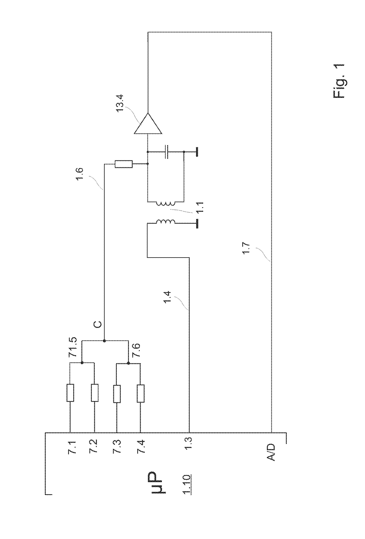
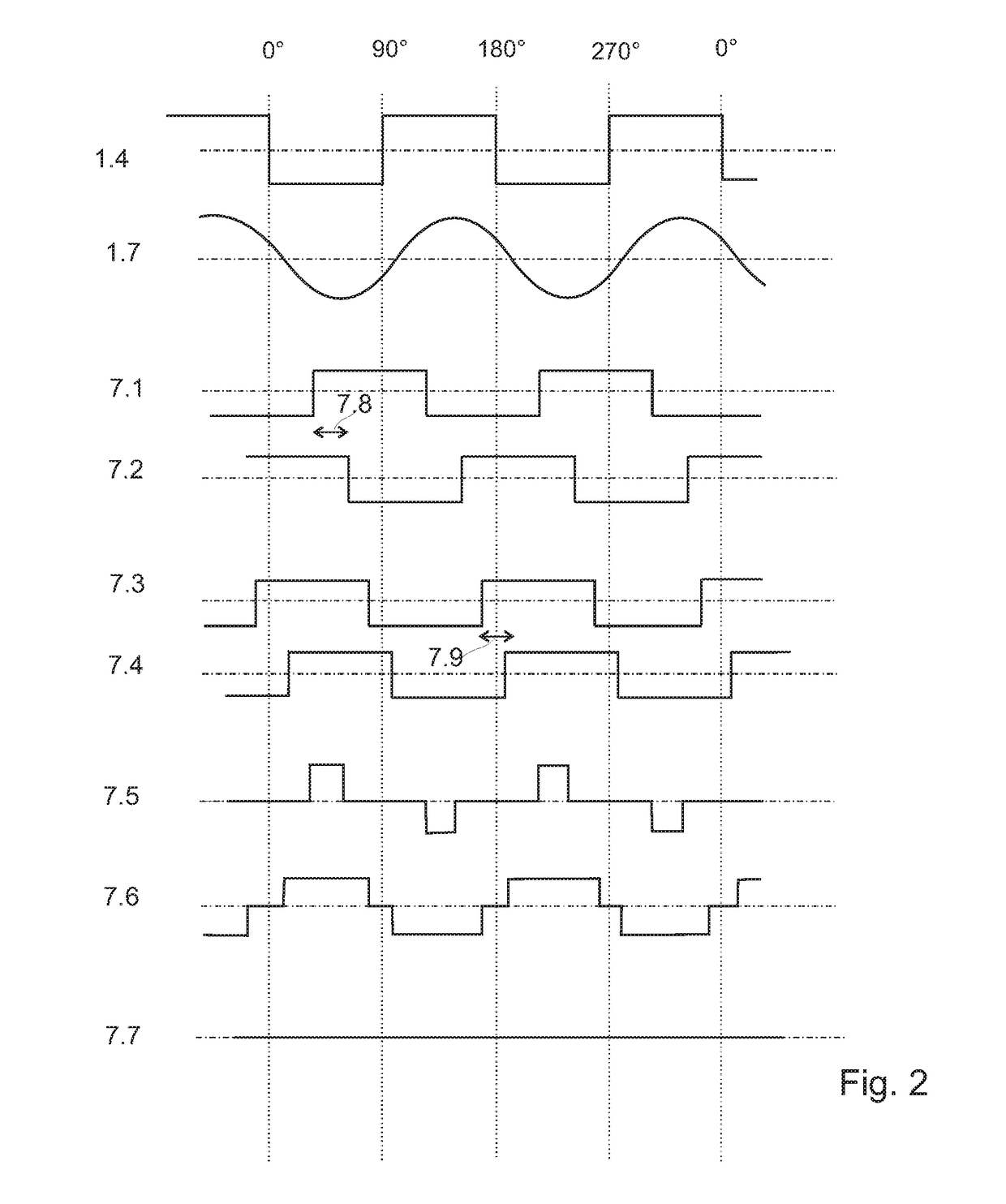
[0018]Preferably, when a relatively high excitation frequency of, for example, 400 kHz is used by way of a combination of a plurality of, for example four, pulse width modulations, a tri-state correction signal is produced that controls the inductive effect of the target to give zero, for example at four points in the

Problems solved by technology

Although today's A/D converters in microprocessors are already very sensitive in order to convert an analogue signal into a digital signal, in some sen

Method used


Image

  • Method for determining at least one physical parameter using a sensor unit
  • Method for determining at least one physical parameter using a sensor unit
  • Method for determining at least one physical parameter using a sensor unit

Examples


Example

[0028]The disclosure is now explained in more detail by way of example, with reference to the attached drawings. However, the exemplary embodiments are only examples, which are not intended to restrict the inventive concept to a particular arrangement. Before the disclosure is described in detail it should be pointed out that it is not restricted to the respective constituent parts of the device and the respective method steps, since these constituent parts and method may vary. The terms used here are merely intended to describe particular embodiments and are not used restrictively. Moreover, where the singular or the indefinite article is used in the description or the claims, this also refers to a plurality of these elements unless the overall context unambiguously indicates otherwise.

[0029]To aid understanding, in the context of the present application the underlying measurement method is first explained with reference to FIGS. 3 to 8, as in the older patent application DE 10 201...


PUM


Abstract

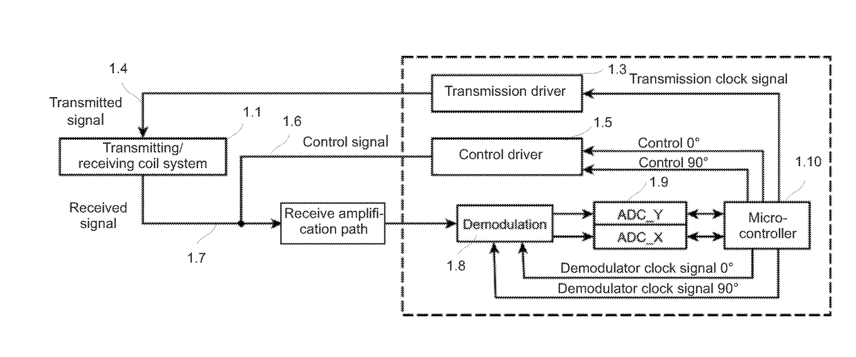
In a method for determining at least one physical parameter, a sensor unit which is activated by at least one periodic excitation (1.4) is provided, wherein the sensor unit has at least one detection region in which changes of the parameter in the surroundings of the sensor unit lead to output signal (1.7) from the sensor unit. The sensor unit is wired such that if there are no changes of the parameter in the detection region the output signal (1.7) is a zero signal or virtually a zero signal at the output of the sensor unit, whereas if there are changes of the parameter in the detection region the output signal (1.7) is a signal that is not zero and has a specific amplitude and phase. In a closed control loop, the non-zero signal in the receive path is adjusted to zero using a control signal to achieve an adjusted state even in the presence of changes of the parameter in the detection region. The control signal is evaluated in order to determine the physical parameter. The output signal (1.7) from the sensor unit is reduced substantially to the fundamental wave of the excitation (1.4) and the output signal (1.7) is controlled to zero in the entire phase space by means of at least one pulse width modulation. A temperature-stable, fully digital measuring system is provided as a result of the fact that the at least one pulse width modulation itself generates a correction signal with a variable pulse width and possibly a variable phase which is then added to the output signal (1.7) from the sensor unit and the output signal is thereby controlled to zero in the entire phase space, wherein the pulse width of the correction signal and/or the phase of the correction signal is/are determined by the deviations of the output signal (1.7) from zero.

Description

CROSS REFERENCE TO RELATED APPLICATIONS[0001]The present disclosure relates to and claims the priority of German patent application 10 2014 007 491.9, filed on 23 May 2014, and German patent application 10 2014 010 671.3, filed on 22 Jul. 2014, the disclosure of which is hereby expressly incorporated by reference into the subject matter of the present application in its entirety.TECHNICAL FIELD[0002]The disclosure relates to a method for determining at least one physical parameter by means of a sensor unit.BACKGROUND[0003]The most diverse methods for determining at least one physical parameter by means of a sensor unit are known from the prior art. These measurement methods frequently have in common a dependence on temperature, which is explained below with reference to inductive measuring systems, even though these statements may also apply to any other principles of measurement as desired, such as in particular capacitive or resistive measuring systems, or indeed optical or chemic...

Claims


Application Information

Patent Timeline
IPC IPC(8): G01V3/10G01N27/02
CPCG01N27/028G01V3/10G01R27/267H01J41/02G01R27/2611G01R27/00H01J41/00G01N27/64G01R27/26
Inventor REIME, GERD
Owner REIME GERD
Learn More