
Display with micro-led front light

Active Publication Date: 2017-03-09
X DISPLAY CO TECH LTD
View PDF6 Cites 90 Cited by
  • Summary
  • Abstract
  • Description
  • Claims
  • Application Information

AI Technical Summary

Benefits of technology

The present invention provides a front light for reflective displays that does not require a light-guide plate or edge emitters. This eliminates the need for expensive and thick optical sheets, resulting in improved performance and reduced size, weight, and thickness of the system. Embodiments of the invention are a thin, single-substrate, integrated front light and touchscreen system that achieves these technical effects.

Problems solved by technology

Light guide plates are expensive optical sheets that absorb some light and add undesirable thickness and weight to the device.

Method used


Image

  • Display with micro-led front light
  • Display with micro-led front light
  • Display with micro-led front light

Examples


Embodiment Construction

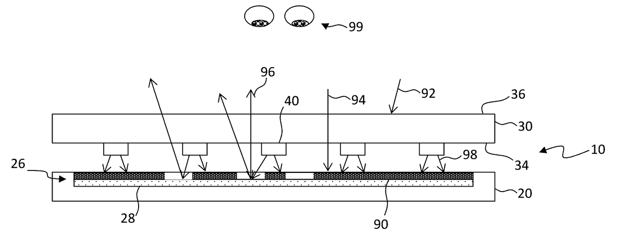
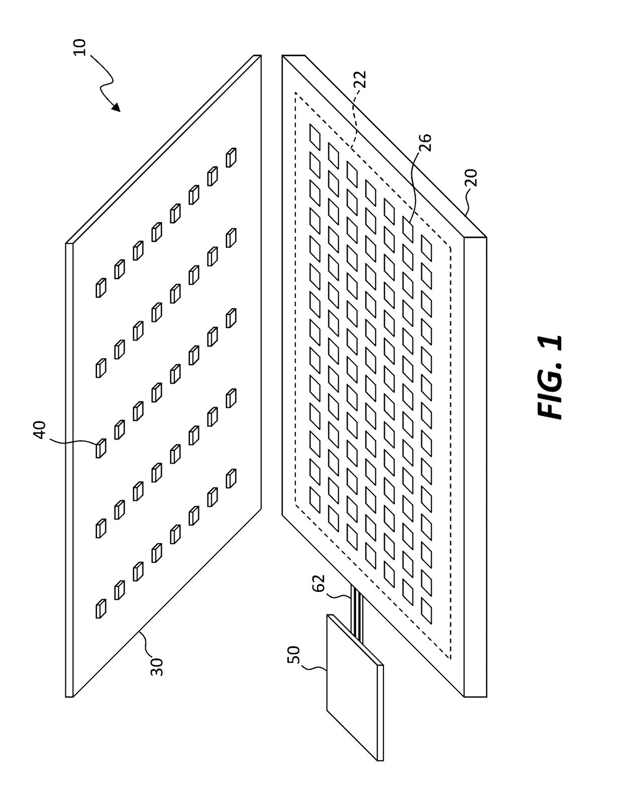
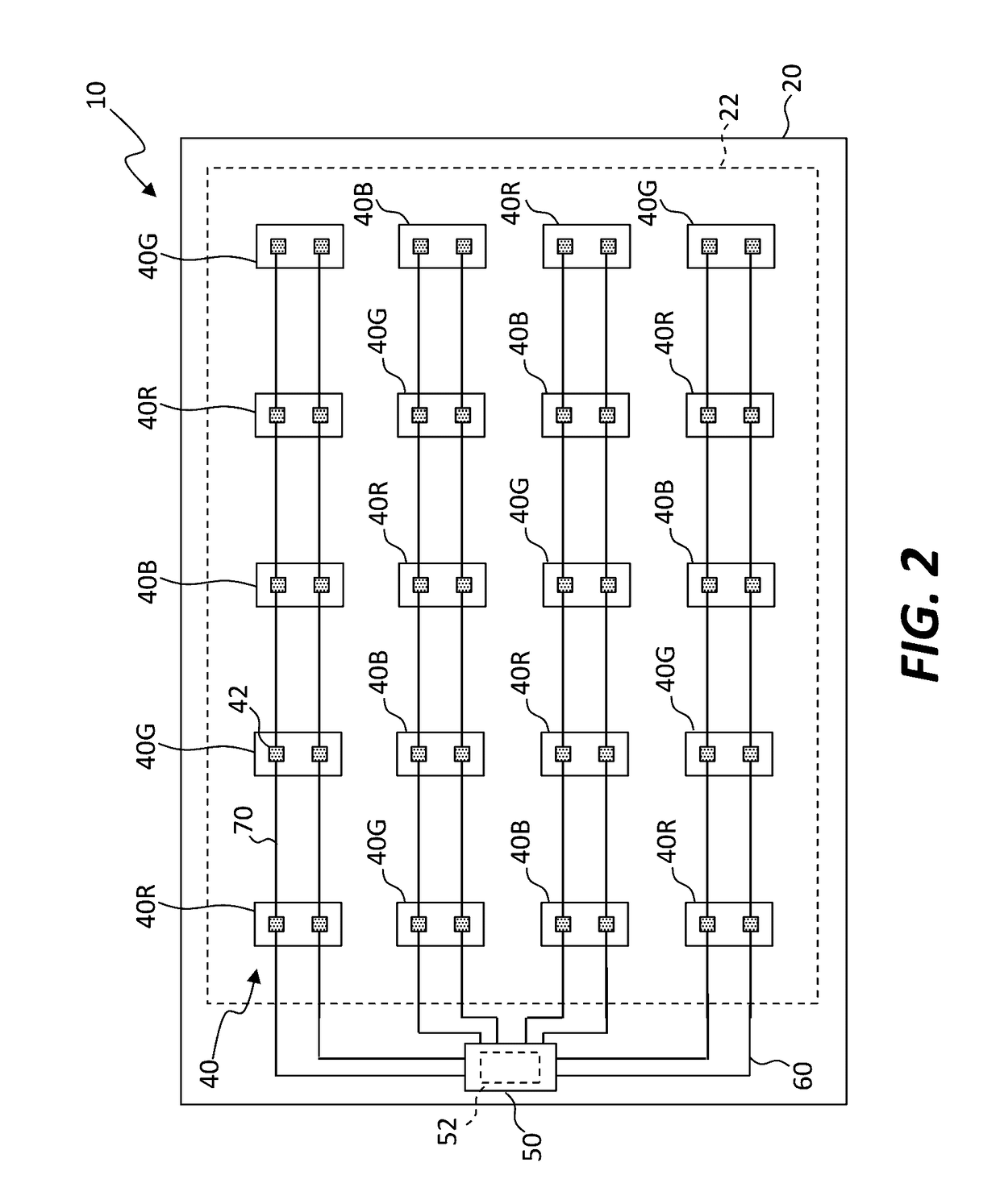
[0058]Referring to the exploded perspective of FIG. 1 and the schematic of FIG. 2, in an embodiment of the present invention a reflective display 10 includes an array of reflective pixels 26 having a display viewing area 22 for viewing electronically displayed information. A layer 30 is located on or over the display viewing area 22 through which the array of reflective pixels 26 is viewed. The array of reflective pixels 26 can be formed on a display substrate 20, for example including glass or plastic. A plurality of micro-LEDs 40 is positioned on or in the layer 30 within the display viewing area 22 and arranged to emit light toward the display viewing area 22. Positioned within the display viewing area 22 means that the plurality of micro-LEDs 40 is within the x-y boundaries of the reflective display viewing area 22 where x and y are orthogonal dimensions parallel to a surface of the reflective display viewing area 22 and largely orthogonal to a viewing direction of the reflectiv...


PUM


Abstract

A reflective display includes an array of reflective pixels in or beneath a display viewing area for viewing electronically displayed information. A layer is located on or over the display viewing area through which the display viewing area is viewed and a plurality of micro-LEDs is located on the layer in the display viewing area and arranged to emit light toward the display viewing area. A plurality of conductors is located on the layer and the conductors are electrically connected to the micro-LEDs. A controller is connected to the conductors to control the micro-LEDs to emit light illuminating the display viewing area.

Description

CROSS REFERENCE TO RELATED APPLICATIONS[0001]Reference is made to commonly assigned U.S. patent application Ser. No. 14 / 754,573 filed Jun. 29, 2015, entitled Small-Aperture-Ratio Display with Electrical Component, to commonly assigned U.S. patent application Ser. No. 14 / 795,831 filed Jul. 9, 2015, entitled Active-Matrix Touchscreen, to commonly assigned U.S. patent application Ser. No. 14 / 822,868 filed Aug. 10, 2015, entitled Compound Micro-Assembly Strategies and Devices, and to commonly assigned U.S. patent application Ser. No. 14 / 743,788, filed Jun. 18, 2015 and titled Micro Assembled LED Displays and Lighting Elements, the contents of each of which are incorporated by reference herein in their entirety.FIELD OF THE INVENTION[0002]The present invention relates to front light illumination for reflective displays and, in certain embodiments, an integrated touch screen.BACKGROUND OF THE INVENTION[0003]Flat-panel displays are widely used in conjunction with computing devices, in port...

Claims


Application Information

Patent Timeline
IPC IPC(8): G06F3/041H01L33/62G09G3/32H01L33/60G06F3/044H01L25/075H01L25/16
CPCG06F3/0412H01L25/0753H01L33/62H01L25/167H01L33/60G09G2300/0426G06F3/044G09G3/32G09G2320/0626G09G2354/00G06F3/0416G02F1/13318G02F1/13338G02F1/133553G02F1/133603G02F2201/50G02F2203/02G06F2203/04111G06F2203/04112G06F3/04164G06F3/0446G06F3/0443G06F3/0445G02F1/133601G02F1/133616
Inventor DEN BOER, WILLEMCOK, RONALD S.
Owner X DISPLAY CO TECH LTD
Learn More