Handlebar and grip apparatus and system

a technology of hand grip and hand grip, which is applied in the direction of steering devices, transportation and packaging, bicycle equipment, etc., can solve the problems of hand discomfort, hand injury, and inability to properly hold the grip

Active Publication Date: 2017-03-02
PADLOC
View PDF18 Cites 4 Cited by
  • Summary
  • Abstract
  • Description
  • Claims
  • Application Information

AI Technical Summary

Benefits of technology

[0013]The disclosed invention relates to a handlebar and grip system comprising: a handlebar, the handlebar comprising: a center portion; a right handle attached to a first end of the center portion, the right handle comprising: a right handle outboard end; a right handle engaging geometry located on the right handle outboard end a left handle attached to the second end of the center portion, the left handle comprising: a left handle outboard end; a left handle engaging geometry located on the left handle outboard end; a right grip configured to slide onto the outboard end of the right handle, the right grip comprising: a right grip central opening; a right grip engaging geometry located in...

Problems solved by technology

However, the clamps or collars tend to be located where a rider would place his or her hands, causing discomfort to the hands, and may cause an inability to properly hold the grips.
Many grips do not provide enough cushion for the ulnar nerve in the hand, and thus can lead to injuries to the hand, such as, but not limited to ulnar neuropathy or handlebar palsy.
Some grips provide for a wing shaped design, to provide for better cushioning near the ulnar nerve, but those wing shaped designs have disadvantages.
Wing shaped grips can lead to twisting of the grips with respect to the handlebar.
It is di...

Method used


Image

  • Handlebar and grip apparatus and system
  • Handlebar and grip apparatus and system
  • Handlebar and grip apparatus and system

Examples


Embodiment Construction

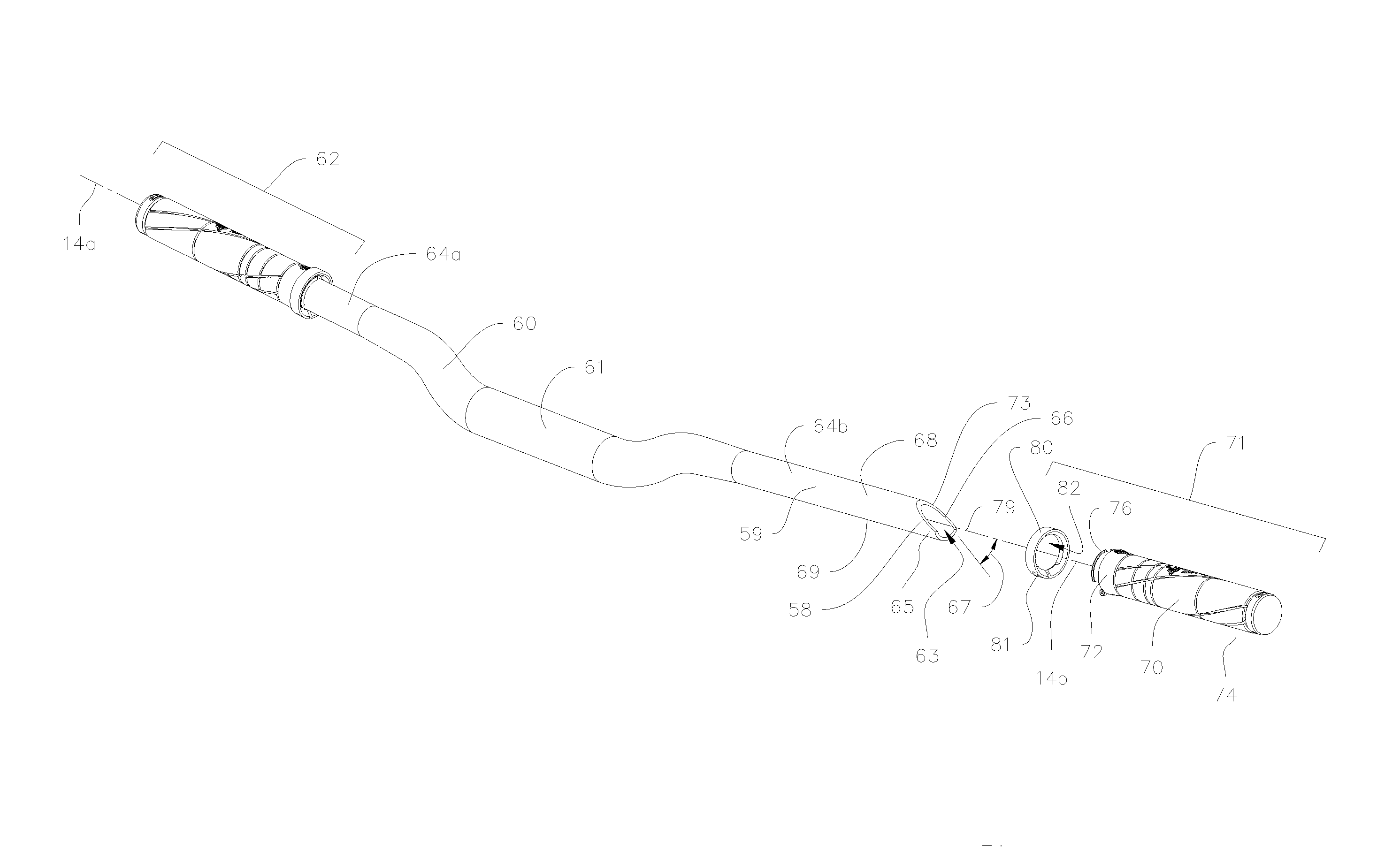
[0052]FIGS. 2a-e describe an embodiment of the present invention where the outboard end 65 of the right handle 64b is manufactured to an angle 67 to the axial axis 14b to create a wedge geometry 73 with a generally planar wedge surface 66 to provide a rotationally keyed engagement and an axial depth stop with the right grip 70 about the axial axis 14b. Handlebar 60 includes a left handle 64a, a right handle 64b, and a center portion 61 for assembly with a central clamping device (not shown) in the conventional manner. The right handle 64b is a tubular element with an external sidewall 59, and end face 58, and a central opening 63 extending therein. The external sidewall 59 also includes an upper surface 68 that generally faces the operator's palm (not shown) and a lower surface 69 opposed to the upper surface and generally facing the ground (not shown). The wedge surface 66 is shown here to be generally aligned along angle 67 such that the lower surface 69 extends axially outwardly ...


PUM


Abstract

A handlebar and grip system comprising: a handlebar, the handlebar comprising: a center portion; a right handle attached to a first end of the center portion, the right handle comprising: a right handle outboard end; a right handle engaging geometry located on the right handle outboard end a left handle attached to the second end of the center portion, the left handle comprising: a left handle outboard end; a left handle engaging geometry located on the left handle outboard end; a right grip configured to slide onto the outboard end of the right handle, the right grip comprising: a right grip central opening; a right grip engaging geometry located in the right grip central opening; a left grip configured to slide onto the outboard end of the left handle; a left grip central opening; a left grip engaging geometry located in the left grip central opening; where the right grip engaging geometry is configured to engage with the right handle engaging geometry such that the right grip will generally be prevented from rotating about the right handle when the right grip has been slid onto the right handle; and where the left grip engaging geometry is configured to engage with the left handle engaging geometry such that the left grip will generally be prevented from rotating about the left handle when the left grip has been slid onto the left handle. A handlebar comprising: a center portion; a right handle attached to a first end of the center portion, the right handle comprising: a right handle outboard end; a right handle engaging geometry located on the right handle outboard end; a left handle attached to the second end of the center portion, the left handle comprising: a left handle outboard end; a left handle engaging geometry located on the left handle outboard end. A grip comprising: a grip central opening; a grip engaging geometry located in the grip central opening.

Description

CROSS-REFERENCES[0001]This patent application claims the benefit of PCT application no. PCT / US2015 / 029524, by applicant PADLOC, LLC, and inventors Jason Moeschler, Chris Feucht, Evan Smith, Mark Slate, Patrick Seidler, and Raphael Schlanger, entitled “HANDLEBAR AND GRIP APPARATUS AND SYSTEM,” filed on May 6, 2015, and which PCT application is fully incorporated by reference herein. This patent application also claims the benefit of provisional patent application No. 61 / 996,920, by Jason Moeschler, Chris Feucht, Evan Smith, Mark Slate, Patrick Seidler, and Raphael Schlanger, entitled “HANDLEBAR GRIP,” filed on May 19, 2014, and which provisional application is fully incorporated by reference herein.TECHNICAL FIELD[0002]The present invention relates to a handlebar and grip apparatus and system, and more specifically to a handlebar and grip apparatus and system that prevents the grip from rotating, and provides cushioning in key area of the hand.BACKGROUND[0003]Current handlebar and gr...

Claims


Application Information

Patent Timeline
IPC IPC(8): B62K21/26B62K21/12
CPCB62K21/12B62K21/26
Inventor MOESCHLER, JASONFEUCHT, CHRISTIANSMITH, EVANSLATE, MARKSEIDLER, PATRICK M.SCHLANGER, RAPHAEL
Owner PADLOC
Why Eureka
Try Eureka