Clear ice maker

a clear, ice maker technology, applied in the field of ice makers, can solve the problems of cloudy appearance of ice cubes, undesirable taste and appearance, and high cost of inclusion in consumer refrigerators and other appliances

Active Publication Date: 2017-02-16
WHIRLPOOL CORP
View PDF0 Cites 0 Cited by
  • Summary
  • Abstract
  • Description
  • Claims
  • Application Information

AI Technical Summary

Benefits of technology

The present invention is an ice maker with a thermally conductive floor and a flexible grid positioned in the water basin to define individual ice cube compartments. The ice maker also includes a thermoelectric plate positioned in thermal contact with the floor of the basin. The invention allows for the automatic ice-making process by rotating the basin and the grid to an inverted position, allowing the ice cubes to be released from the grid. Additionally, the invention includes a tray for making clear ice from the floor upward, with a thermally conductive floor and a polymeric sidewall frame integrally molded to the floor. The technical effects of the invention include efficient ice-making and improved ice quality.

Problems solved by technology

During the ice making process when water is frozen to form ice cubes, trapped air tends to make the resulting ice cubes cloudy in appearance.
The trapped air results in an ice cube which, when used in drinks, can provide an undesirable taste and appearance which distracts from the enjoyment of a beverage.
Clear ice requires processing techniques and structure which can be costly to include in consumer refrigerators and other appliances.

Method used


Image

  • Clear ice maker
  • Clear ice maker
  • Clear ice maker

Examples


Embodiment Construction

[0052]For purposes of description herein, the terms “upper,”“lower,”“right,”“left,”“rear,”“front,”“vertical,”“horizontal,” and derivates thereof shall relate to the ice maker assembly 52, 210 as oriented in FIG. 2 unless stated otherwise. However, it is to be understood that the ice maker assembly may assume various alternative orientations, except where expressly specified to the contrary. It is also to be understood that the specific devices and processes illustrated in the attached drawings, and described in the following specification are simply exemplary embodiments of the inventive concepts defined in the appended claims. Hence, specific dimensions and other physical characteristics relating to the embodiments disclosed herein are not to be considered as limiting, unless the claims expressly state otherwise.

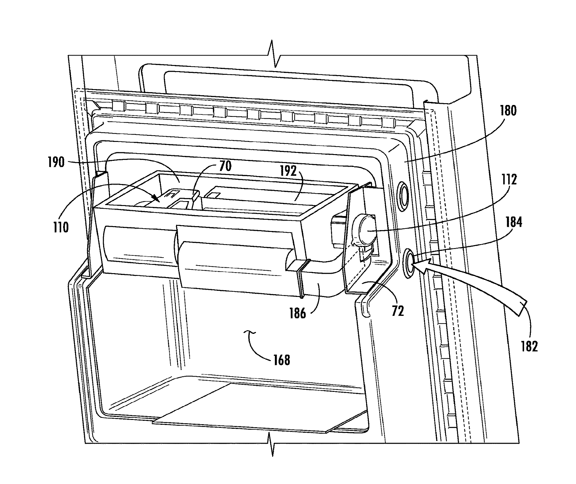
[0053]Referring initially to FIGS. 1-2, there is generally shown a refrigerator 50, which includes an ice maker 52 contained within an ice maker housing 54 inside the refri...


PUM


Abstract

An ice making tray has a water basin with a thermally conductive floor and a flexible grid positioned therein to define a plurality of ice making compartments. A motor is coupled to the basin to rotate the basin and grid to an inverted position, and a link is coupled between the motor and drive such that the grid is rotatable out of the basin and is flexed to release ice cubes formed therein.

Description

CROSS-REFERENCE TO RELATED APPLICATIONS[0001]The present application is a continuation of U.S. patent application Ser. No. 13 / 713,244 filed Dec. 13, 2012, entitled CLEAR ICE MAKER, the entire disclosure of which is hereby incorporated herein by reference.[0002]The present application is also related to, and hereby incorporates by reference the entire disclosures of, the following applications for United States Patents: U.S. patent application Ser. No. 13 / 713,283, entitled “Ice Maker with Rocking Cold Plate,” filed on Dec. 13, 2012, now U.S. Pat. No. 9,410,723; U.S. patent application Ser. No. 13 / 713,199, entitled “Clear Ice Maker with Warm Air Flow,” filed on Dec. 13, 2012; U.S. patent application Ser. No. 13 / 713,296, entitled “Clear Ice Maker with Varied Thermal Conductivity,” filed on Dec. 13, 2012; U.S. patent application Ser. No. 13 / 713,206, entitled “Layering of Low Thermal Conductive Material on Metal Tray,” filed on Dec. 13, 2012, now U.S. Pat. No. 9,310,115; U.S. patent appl...

Claims


Application Information

Patent Timeline
Patent Type & Authority Applications(United States)
IPC IPC(8): F25C1/18F25C5/18F25C1/24F25B21/02F25C5/06
CPCF25C1/18F25B21/02F25C2305/022F25C1/243F25C5/182F25C5/06F25C1/22F25C5/22F25C2305/0221F25C5/04
Inventor BOARMAN, PATRICK J.THOMAS, MARK E.
Owner WHIRLPOOL CORP
Why Eureka
Try Eureka