
Dual Lumen Endobronchial Tube Device

a technology of endobronchial tube and lumen, which is applied in the direction of medical devices, respiratory devices, other medical devices, etc., can solve the problems of difficult insertion and even airway injury, design suffers from several major drawbacks, and affects clinical care negatively

Active Publication Date: 2017-02-16
RGT UNIV OF CALIFORNIA
View PDF13 Cites 26 Cited by
  • Summary
  • Abstract
  • Description
  • Claims
  • Application Information

AI Technical Summary

Benefits of technology

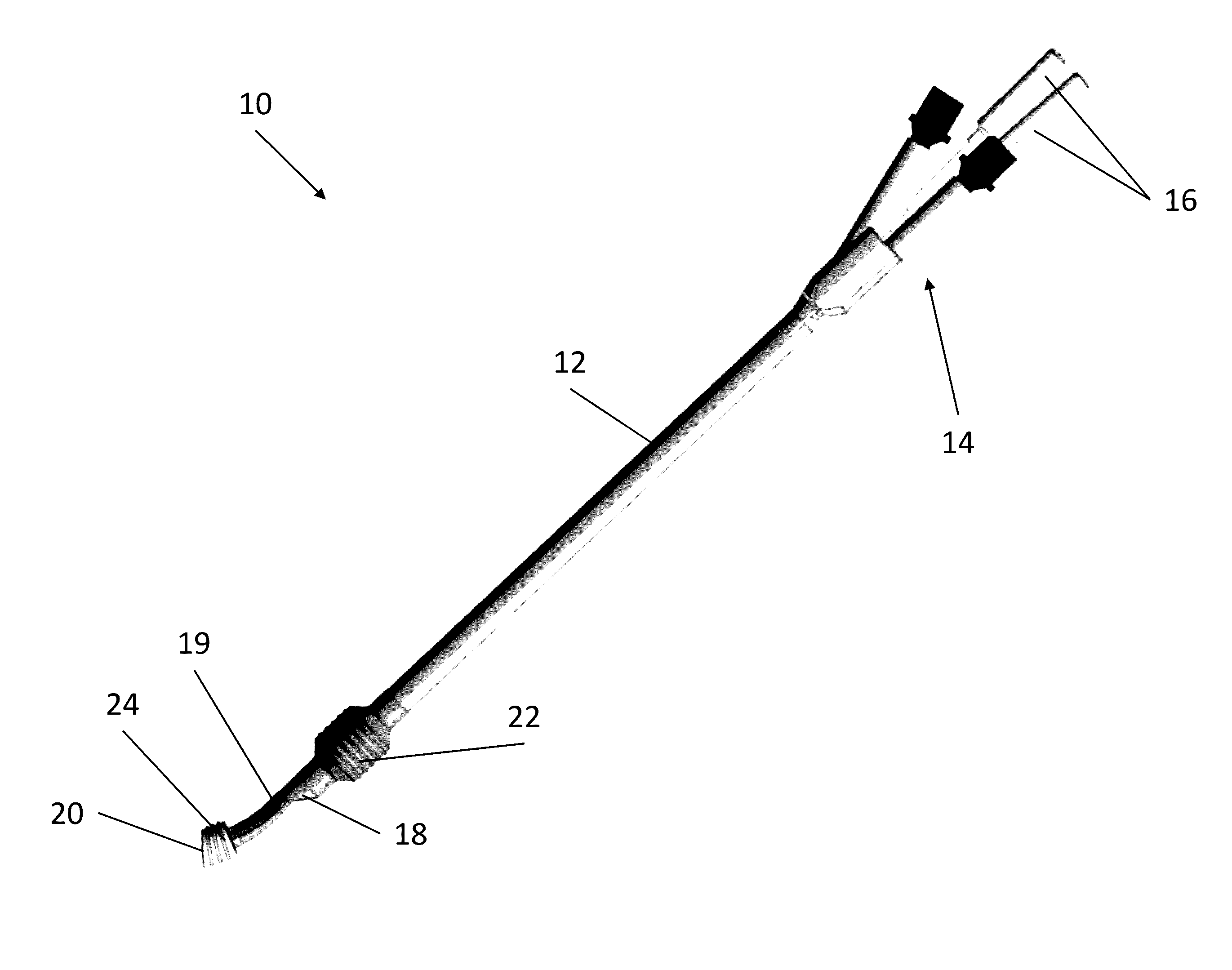
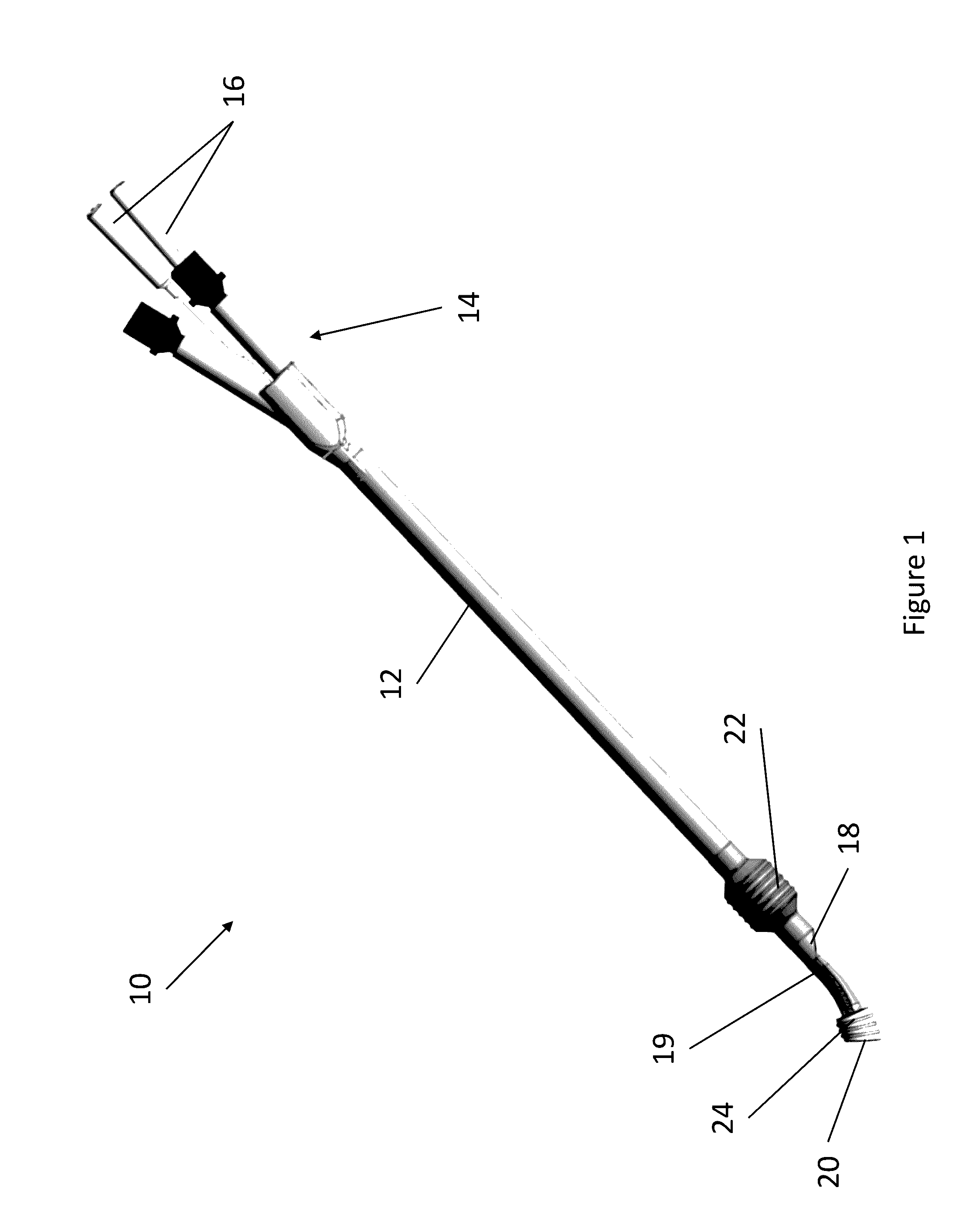
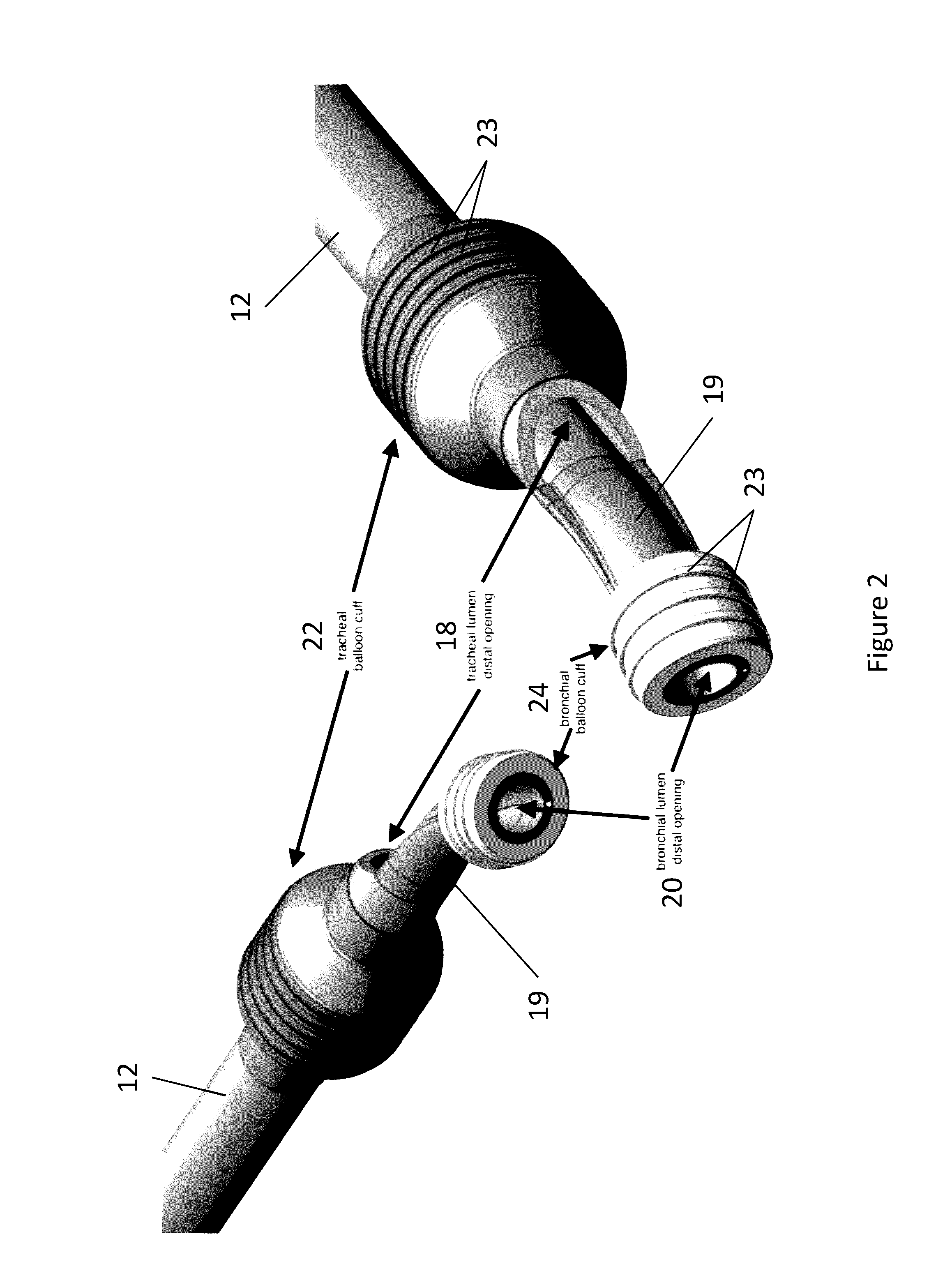
The present invention is related to a device for use in the airways, which has a straight shaft and a curved bronchial tube. The device has a tracheal lumen and a bronchial lumen, which are separated by a flexible semilunar membrane. The device also has a balloon cuff at the distal end of the shaft and a balloon cuff at the bronchial end. The device can be used as a universal dual lumen endobronchial device or as a double clamp device. The invention provides improved airway management for patients with respiratory illnesses.

Problems solved by technology

The DLT design suffers from several major drawbacks that negatively affect clinical care.
The combination of their large and bulky design and their stiffness with pre-set angles can lead to difficult insertion and even airway injury.
Even if insertion is atraumatic, the DLT's large external diameter increases the pressure on the vocal cords, potentially injuring these delicate structures, especially during prolonged intubations.
The second major design drawback is the relatively small size of the ventilation passages in the current DLT.
Even the current bulky design houses two relatively small diameter channels, thus limiting the size of bronchoscopes, suction catheters, and other instruments that could be inserted into the lungs during use.
Once the bronchoscopy is completed, the endotracheal tube must be removed and a DLT put in its place, a procedure that can be fraught with risk.
The limited lumen diameter of DLTs poses a special clinical challenge when a patient is bleeding from one lung and lung isolation is warranted.
Although a DLT is ideal for lung isolation to prevent flooding the good lung with blood (possibly causing patient asphyxiation and death), placement of a DLT severely limits one's ability to perform the diagnostic and therapeutic bronchoscopy necessary to treat this medical emergency.
A third major limitation is that the DLT's long tube length combined with its small diameter lumens make even a small bronchoscope (4.0 mm OD) difficult to insert due to significant friction between the scope shaft and tube inner diameter (ID).
Because these lubricants inevitably dry up or get consumed in the process of the examination, the bronchoscope is often difficult to slide in the device and may even sustain damage or become stuck in the tube shaft.
A fourth major limitation of the standard DLT is that its tracheal and bronchial balloon cuffs are the standard elliptical shape with smooth surfaces.
Once inflated, and in the moist setting of the human airway, these balloons easily slip, leading to device dislodgement.
Movement of 10 mm or even less can lead to clinically significant device malpositioning.
Such dislodgement can be at a minimum a significant disruption to the surgery given the loss of lung isolation, and at the extreme can cause severe life threatening hypoxemia (from obstructed oxygen flow and / or lung contamination).
A fifth significant limitation is that the DLT comes in two different configurations, left-sided and right-sided, depending on which bronchus the distal tip is expected to reside in.
A sixth significant limitation involves the need for clamping one limb of a standard Carlens Y adapter to initiate one lung ventilation (OLV).
The weight of this clamp would often torque the whole tube assembly and cause a dislodgement.
Changing from one external clamp to two integrated clamps raises the potential risk that both clamps are simultaneously closed accidentally, as could happen when the ventilation is switched from one lung to the other.
Failure to recognize this error could lead to severe hypoxemia and even death caused by the inability to ventilate the patient and the lack of recognition that this is a device malfunction and not a patient complication.
A seventh significant limitation is the inability to directly measure the pressure in the balloon cuffs.
The lack of being able to measure the real time pressure in the balloon cuff puts the patient at potential risk of tracheal / bronchial injury.

Method used


Image

  • Dual Lumen Endobronchial Tube Device
  • Dual Lumen Endobronchial Tube Device
  • Dual Lumen Endobronchial Tube Device

Examples


experimental examples

[0070]The invention is further described in detail by reference to the following experimental examples. These examples are provided for purposes of illustration only, and are not intended to be limiting unless otherwise specified. Thus, the invention should in no way be construed as being limited to the following examples, but rather, should be construed to encompass any and all variations which become evident as a result of the teaching provided herein.

[0071]Without further description, it is believed that one of ordinary skill in the art may, using the preceding description and the following illustrative examples, utilize the present invention and practice the claimed methods. The following working examples therefore, specifically point out the preferred embodiments of the present invention, and are not to be construed as limiting in any way the remainder of the disclosure.

example 1

Distal Balloon Cuff Development

[0072]A double lumen endotracheal tube (DLT) contains a distal component that sits in the mainstem bronchus. A balloon cuff is inflated to create an air seal necessary for positive pressure ventilation. There are two configurations: a left sided configuration and a right sided configuration. They are named based on the mainstem bronchus that the distal component resides. Because the anatomy of the left and right-sided mainstem bronchus differs, the design of the distal component, including the balloon cuff, also differs. The right mainstem bronchus is short as compared to the left mainstem bronchus, and if the left DLT distal component design were to be used in the right mainstem, it would likely occlude the opening to the right upper lobe. For this reason, a different design, encompassing an off center balloon cuff with a side peering orifice, is used for the R sided DLT. See FIG. 11 for details about right vs. left bronchus, and FIG. 12 for tradition...

example 2

Membrane Durability Test

[0082]The present study examines the durability of a 0.5 mm semilunar membrane in response to puncture from endotracheal tube stylets or other sharp, hard objects inserted into the lumen of an endotracheal tube.

[0083]The semilunar orifice is tested given that it has the smallest inner diameter (ID) and needs to deform to accept a stylet, maximizing the friction and thus the chance that the membrane will perforate. The full-length extruded shaft with lubricious coating applied to the internal diameter of both lumens was tested, although the device was dry to maximize friction and to take the coating out of the equation. A 15 mm universal connector was attached to the proximal end of the semilunar lumen, completely obliterating both lumens on that side. On the distal end, a round tube was inserted such that the other lumen (round) is still patent and in continuity with the atmosphere, and the connection between the tube and semilunar lumen was silicone sealed t...


PUM


Abstract

The present invention provides improved dual lumen endobronchial tube devices. The dual lumen endobronchial tube devices feature a universal design for left or right mainstem bronchus insertion. The dual lumen endobronchial tube devices also feature enhanced balloon cuff designs to minimize dislodgement while maintaining proper airway sealing. The present invention also includes water activated lubricious coating inside the shaft to reduce friction during insertion of a bronchoscope into the airway. The present invention also provides improved double clamps that prevent the accidental clamping of both tubes of a Y-adapter.

Description

CROSS-REFERENCE TO RELATED APPLICATIONS[0001]This application is a continuation-in-part of U.S. patent application Ser. No. 13 / 829,509, filed Mar. 14, 2013, which is entitled to priority to U.S. Provisional Patent Application No. 61 / 690,867, filed Jul. 6, 2012, the contents of which are each incorporated by reference herein in their entirety. This application is also entitled to priority to U.S. Provisional Patent Application No. 62 / 285,592, filed Nov. 3, 2015, which is incorporated herein by reference in its entirety.BACKGROUND OF THE INVENTION[0002]Lung isolation and single lung ventilation are routinely instituted during thoracic surgery. Surgery involving the lung or the contents of the thorax often requires cessation of ventilation to one lung for two main reasons: 1) to keep the lung immobile while surgery on it is performed and 2) to deflate the lung for better visualization of thoracic structures. Other indications for lung isolation include: 1) containment of unilateral pul...

Claims


Application Information

Patent Timeline
Patent Type & Authority Applications(United States)
IPC IPC(8): A61M16/04A61M16/08
CPCA61M16/0486A61M16/0459A61M16/0833A61M2205/3331A61M2016/0027A61M2016/003A61M2205/3368A61M16/0445A61M16/044A61M2205/0222A61M2205/0238A61M16/0404A61M16/0475A61M39/105A61M39/287A61M2039/082A61M2039/1083A61M2039/1088
Inventor HOFTMAN, NIRMAHAJAN, AMANHOFTMAN, MIKE
Owner RGT UNIV OF CALIFORNIA
Learn More