
Pixel circuit, driving method thereof and display device

a technology of pixel circuit and display device, applied in the field of display technology, can solve problems affecting the display performance of the entire imag

Active Publication Date: 2017-02-09
BOE TECH GRP CO LTD +1
View PDF3 Cites 14 Cited by
  • Summary
  • Abstract
  • Description
  • Claims
  • Application Information

AI Technical Summary

Benefits of technology

The present invention provides a pixel circuit that can prevent uneven display brightness caused by threshold drift. This is achieved through a threshold compensation module which cancels out the threshold voltage of the drive module by introducing a compensation voltage that sets the voltage on the control terminal of the drive module to be a sum of the threshold voltage of the drive module and the operating voltage. This results in a driving current that is not affected by the threshold voltage of the drive module, solving the problem of uneven display brightness.

Problems solved by technology

Due to process technology, device aging and other reasons, in an original 2T1C driving circuit (including two thin-film transistors and a capacitor), the threshold voltage on the driving TFTs of the respective pixels is uneven, thereby the current flowing through the OLED in each pixel is varied, the display brightness is uneven, thus affecting the display performance of the entire image.

Method used


Image

  • Pixel circuit, driving method thereof and display device
  • Pixel circuit, driving method thereof and display device
  • Pixel circuit, driving method thereof and display device

Examples


Embodiment Construction

[0032]In order to render the object, solutions and advantages of the present invention more clearly, the technical solutions of the embodiments of the present invention will be described clearly and thoroughly in conjunction with the accompanying drawings.

[0033]Apparently, the described embodiments are merely a part, rather than all of the embodiments of the present invention. Based on the embodiments of the present invention, other embodiments can be obtained by those skilled in the art without creative work, and these embodiments also falls within the scope of the present invention.

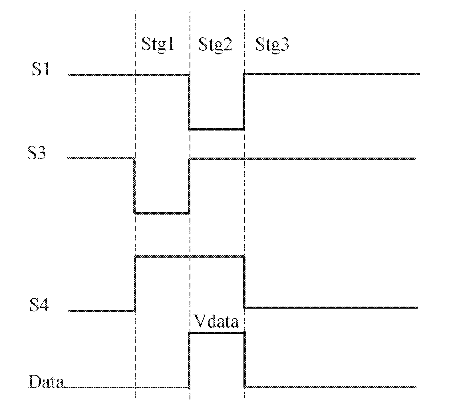
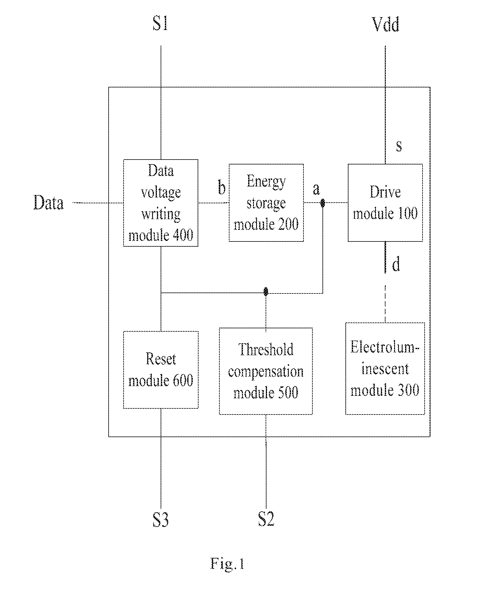
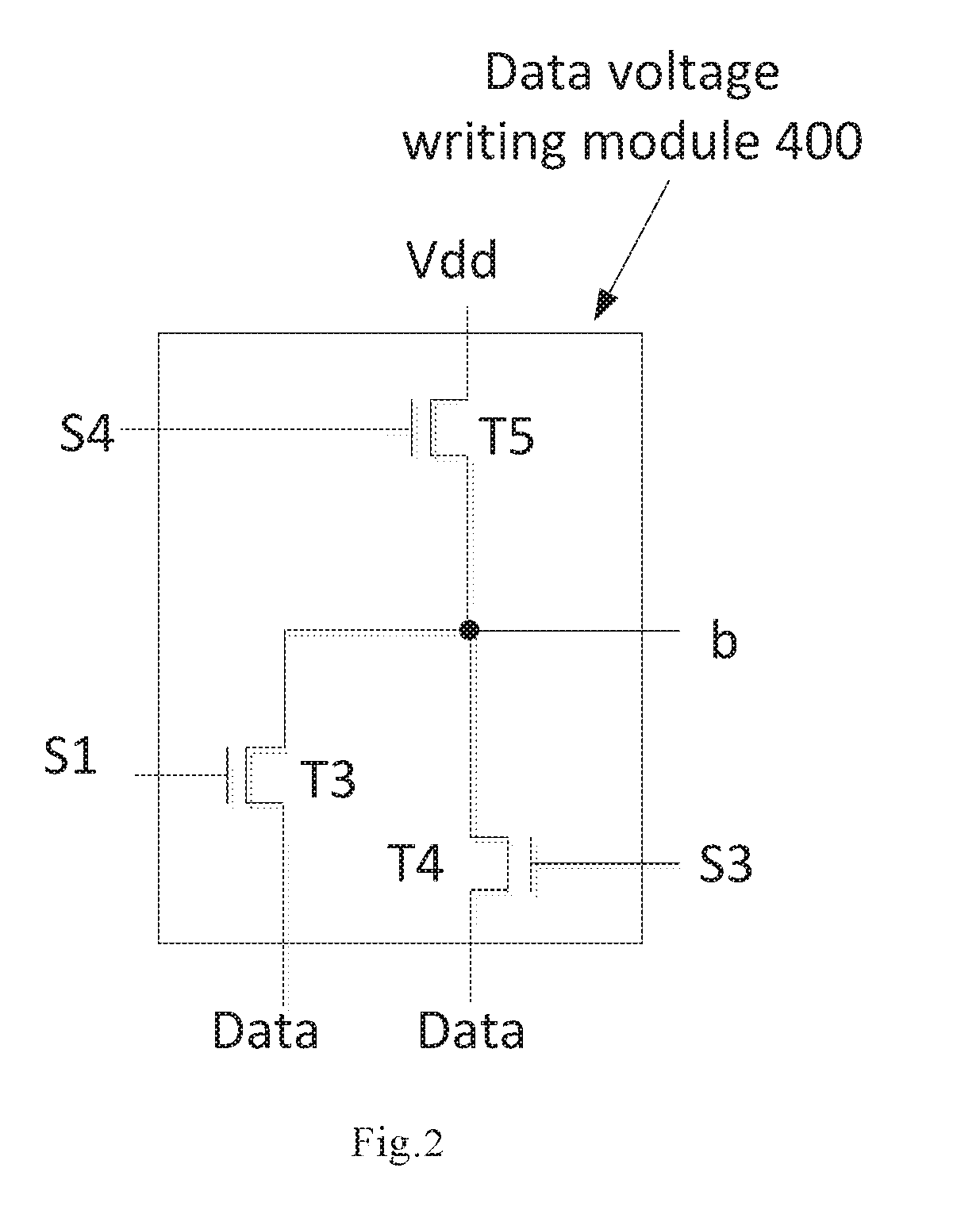
[0034]According to an embodiment of the present invention, as shown in FIG. 1, there is provided a pixel circuit comprising: a drive module 100, an energy storage module 200, an electroluminescent module 300, a data voltage writing module 400, a threshold compensation module 500 and a reset module 600, and further comprising an operating voltage input terminal Vdd, a data voltage input terminal Data, a ...


PUM

PropertyMeasurementUnit
voltageaaaaaaaaaa
threshold voltageaaaaaaaaaa
data voltageaaaaaaaaaa

Abstract

The present invention provides a pixel circuit, a driving method thereof and a display device. The pixel circuit comprises a drive module, an energy storage module, an electroluminescent module, a data voltage writing module, a threshold compensation module and a reset module, and also comprises an operating voltage input terminal, a data voltage input terminal and a plurality of control signal input terminal. The threshold compensation module is capable of introducing the voltage on the compensation voltage input terminal so as to set the voltage on the control terminal of the drive module to be a sum of the threshold voltage of the drive module and the operating voltage, thus the driving current flowing through the electroluminescent units is not affected by the threshold voltage of corresponding drive modules, such that the problem of uneven display brightness caused by the threshold voltage drift of driving transistors can be solved.

Description

FIELD OF THE INVENTION[0001]The present invention relates to the field of display technology, and more particularly to a pixel circuit, a driving method thereof and a display device.BACKGROUND OF THE INVENTION[0002]Organic Light Emitting Diode (OLED) has become a popular field in the flat panel display researching. As a current-controlled light-emitting device. OLED has being increasingly applied in the field of high-performance display, due to the characteristics such as self-emission, fast response, wide viewing angle and capable of being fabricated on flexible substrate. Currently, in the display field of phone, PDA, digital cameras and the like, OLED has begun to replace the traditional LCD (Liquid Crystal Display) display. Pixel driving. circuit design is a key technical content of OLED display, which has important significance of research. Different from TFT (Thin Film Transistor)-LCD which controls brightness by using stable voltage, OLED is of a current driving type which re...

Claims


Application Information

Patent Timeline
Patent Type & Authority Applications(United States)
IPC IPC(8): G09G3/3258G09G3/3291G09G3/3208
CPCG09G3/3258G09G3/3291G09G2300/0809G09G2300/043G09G2320/045G09G2310/08G09G2300/0819G09G2300/0842G09G2300/0861G09G3/3233
Inventor WANG, BOXUAN, MINGHUAZHANG, YI
Owner BOE TECH GRP CO LTD
Learn More