
Nail

a technology for nails and screws, applied in the field of nails, can solve the problems of increasing cost, bending the nail in a bent manner, and easy collapse of the recessing groove wall in the overall periphery of the recessing cavity,

Active Publication Date: 2017-02-02
TANEICHI KAORU
View PDF6 Cites 4 Cited by
  • Summary
  • Abstract
  • Description
  • Claims
  • Application Information

AI Technical Summary

Benefits of technology

The present invention aims to provide a nail that can be easily obtained and driven in a straight manner even when hitting a hard knot. The tip end portion of the nail is designed in a circular conical shape or polygonal pyramidal shape, which requires only a hardening treatment, such as quenching or plastic forging. This makes the processing easier as compared to previous nails where a recessing groove wall is formed in an overall periphery of a recessing cavity.

Problems solved by technology

However, the nail has a disadvantage in that when the tip end portion hits a knotty portion, the nail is driven in a bent manner.
However, when this drive nail is used, there is a disadvantage in that, when the tip end portion hits a knot, the recessing groove wall in the overall periphery of the recessing cavity easily collapses because the drive nail is composed of a soft iron material to meet the Japanese Industrial Standards.
In addition, there is also a disadvantage in that work involved in forming the recessing groove wall in the overall periphery of the recessing cavity is painstaking and cost increases.

Method used


Image

  • Nail
  • Nail
  • Nail

Examples


Embodiment Construction

[0037]The present invention will be described in detail based on embodiments for carrying out the present invention shown in the drawings.

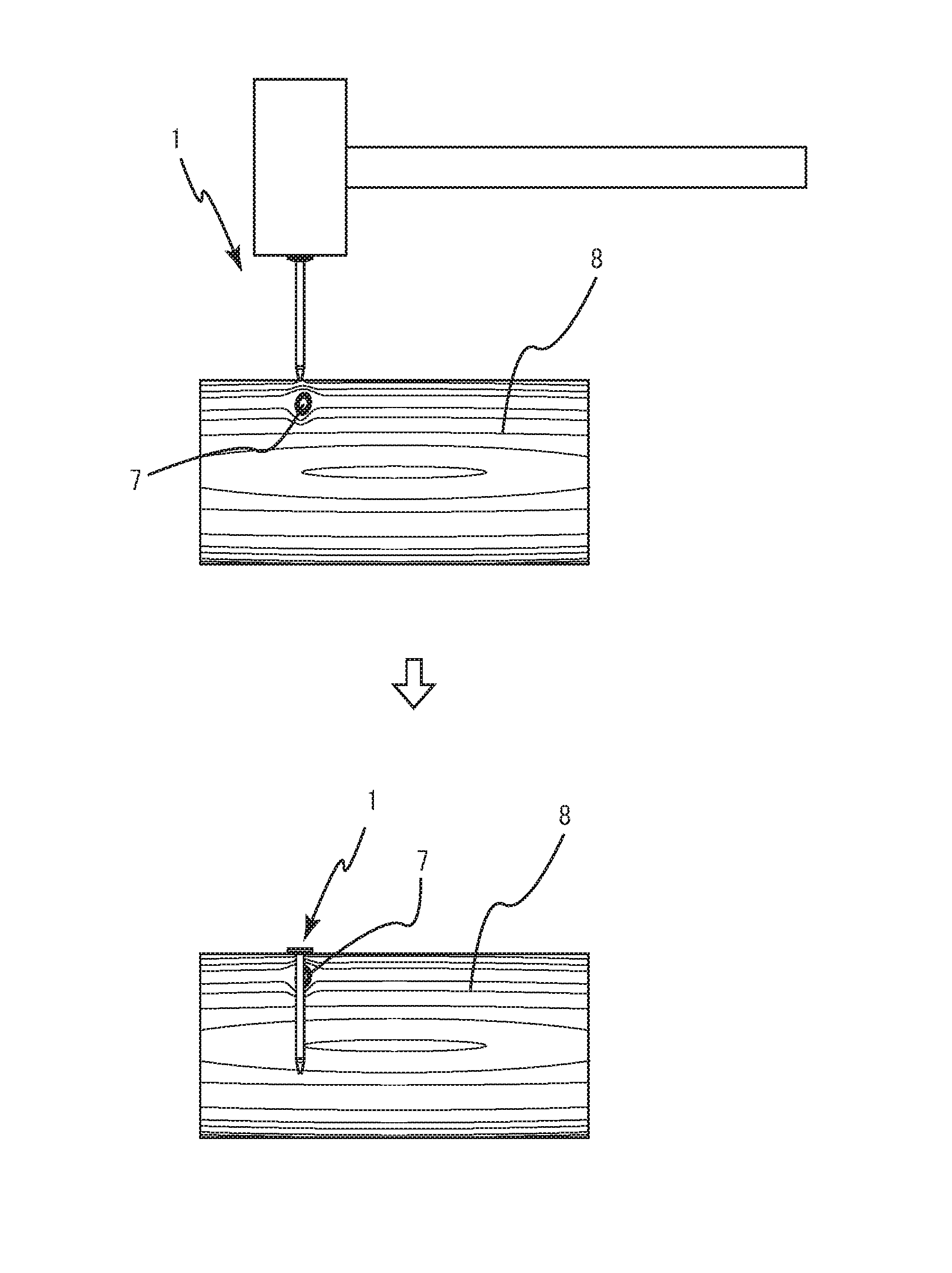
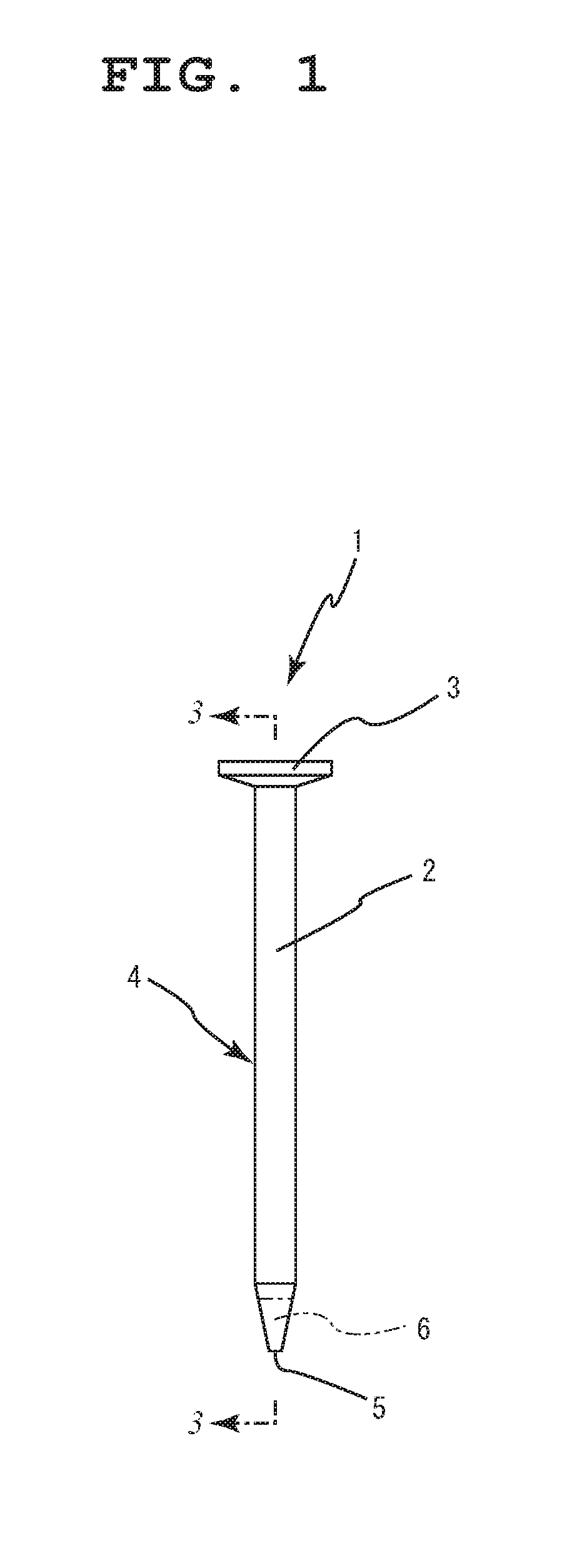
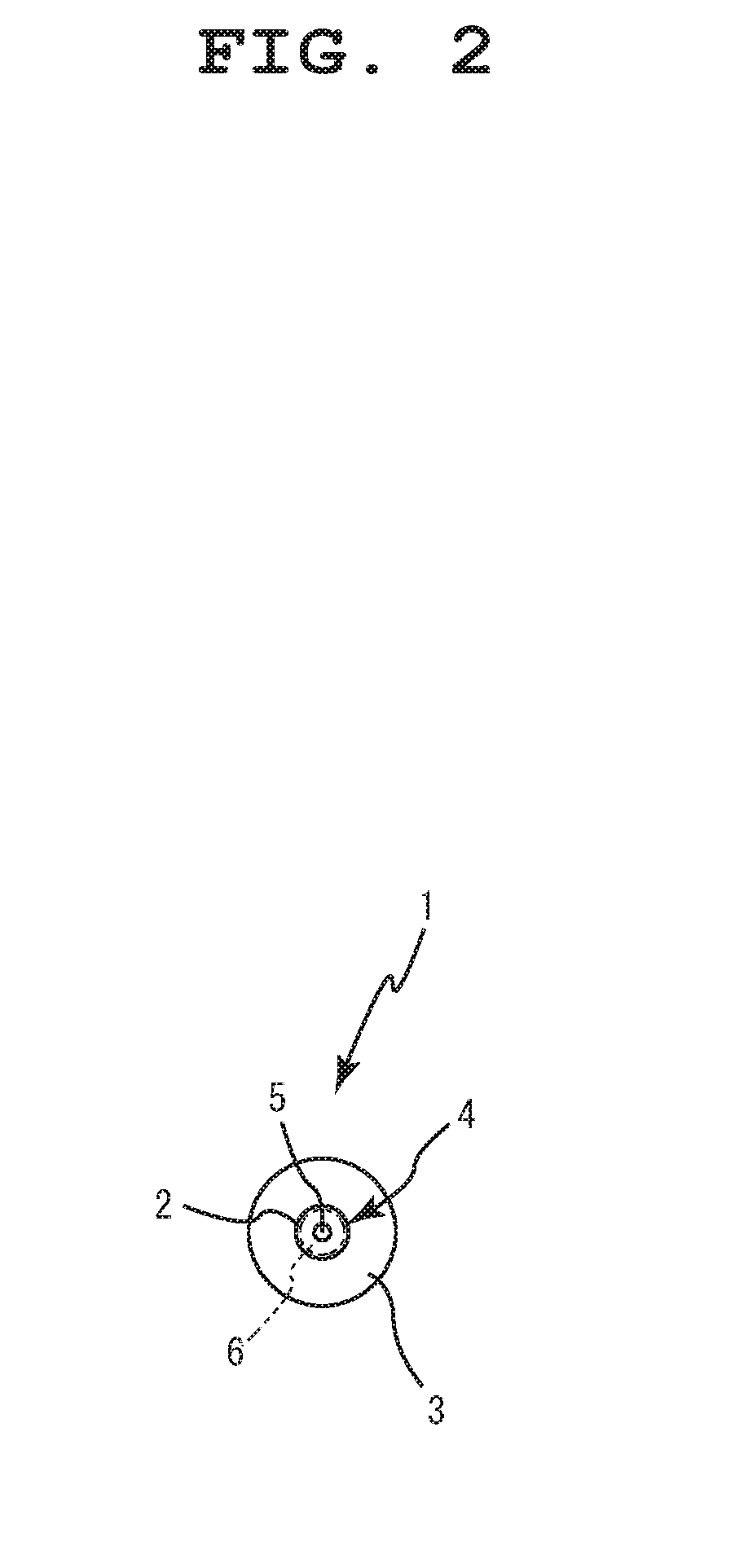
[0038]According to a first embodiment for carrying out the present invention shown in FIG. 1 to FIG. 5, reference number 1 represents a nail of the present invention that is composed of a soft iron material. The nail 1 is configured by a main nail body 4 and a tip end portion 5. In the main nail body 4, a head portion 3 is formed in an upper end portion of a cylindrical columnar body 2. The tip end portion 5 is formed in a lower end portion of the main nail body 4 and has a circular conical shape. As shown in FIG. 4, heat treatment by quenching is performed on the tip end portion 5, and a tip end portion hardening-treatment portion 6 is thereby formed.

[0039]When the nail 1, configured as described above, is driven into a piece of lumber 8 at location where a knot 7 is present, the tip end portion 5 of the nail 1 can be easily driven to the locatio...


PUM


Abstract

A nail that is configured by: a nail main body composed of a soft iron material in which a head portion is formed in an upper end portion of a columnar body; and a tip end portion having a circular conical shape or a polygonal pyramidal shape that is formed in a lower end portion of the nail main body, in which the tip end portion is subjected to a tip end portion hardening treatment by quenching or plastic forging. The nail meets the Japanese Industrial Standards, is capable of being driven in a straight manner even when the tip end portion hits a hard knot, and is capable of being manufactured with relative ease.

Description

BACKGROUND OF THE INVENTION[0001]1. Field of the Invention[0002]The present invention relates to a nail that is used, for example, to join lumber and the like.[0003]2. Description of the Related Art[0004]Related art includes Japanese Patent Laid-open Publication No. 2004-32912 and Japanese Patent Laid-open Publication No. 2003-97523.[0005]Since the past, nails have been made of soft iron materials. A head portion is formed in an upper end portion of a columnar body. A circular conical or pyramidal tip end portion is formed in a lower end portion.[0006]A nail that is formed in this manner can be smoothly driven into a piece of lumber in a section that has no knots, with the circular conical or pyramidal tip end portion. However, the nail has a disadvantage in that when the tip end portion hits a knotty portion, the nail is driven in a bent manner.[0007]To solve this disadvantage, a following drive nail is considered. A lower end of the drive nail is formed into the shape of an invert...

Claims


Application Information

Patent Timeline
IPC IPC(8): F16B15/02
CPCF16B15/02F16B15/00
Inventor TANEICHI, KAORU
Owner TANEICHI KAORU
Learn More