
Muffler for pneumatic power tool and pneumatic power tool incorporating the same

a pneumatic power tool and muffler technology, applied in the field of mufflers for pneumatic power tools, can solve the problems of not being used, not always used, and affecting the operation of operators and others located nearby

Active Publication Date: 2017-02-02
EXHAUST TECH
View PDF30 Cites 2 Cited by
  • Summary
  • Abstract
  • Description
  • Claims
  • Application Information

AI Technical Summary

Benefits of technology

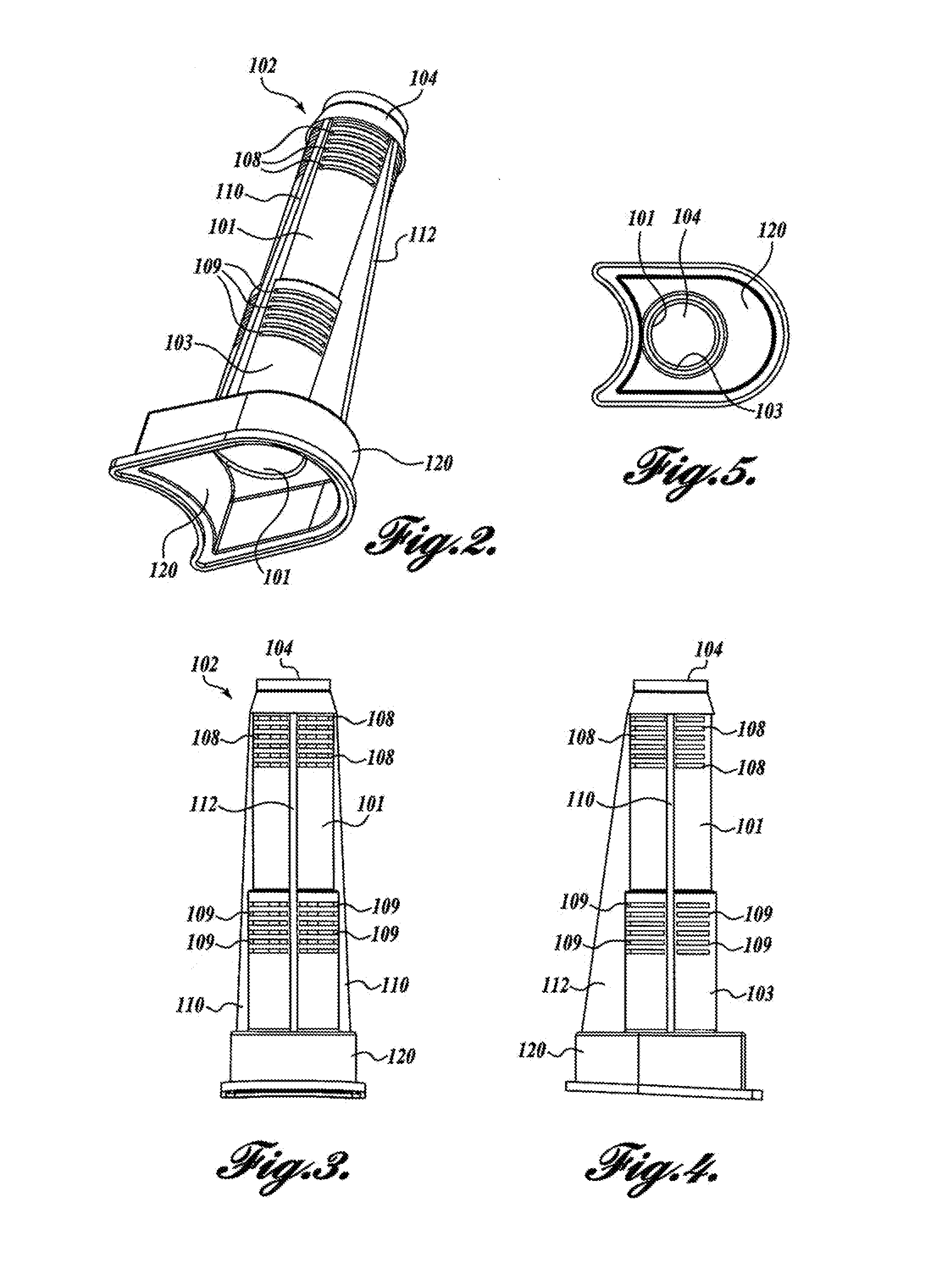
The present patent describes a muffler assembly for a pneumatic power tool. The muffler assembly includes a tube member with an upper and lower segment, where the upper segment has a smaller diameter and the lower segment has a larger diameter. The tube member has a plurality of vents and a continuous surface to inhibit fluid communication with the interior volume. The muffler assembly also includes a filter panel and flanges that define channels between the filter panel and the exterior surface of the tube member. Additionally, the muffler assembly has a receptacle and a diffuser panel. Overall, the muffler assembly improves the performance of the pneumatic power tool and reduces the noise levels.

Problems solved by technology

When exhaust air is vented from the power tool, a considerable amount of noise and particulate debris are generated, potentially causing auditory and / or respiratory damage to the operator and others located nearby.
Although earplugs and facemasks are often available, they are not always used.

Method used


Image

  • Muffler for pneumatic power tool and pneumatic power tool incorporating the same
  • Muffler for pneumatic power tool and pneumatic power tool incorporating the same
  • Muffler for pneumatic power tool and pneumatic power tool incorporating the same

Examples


Embodiment Construction

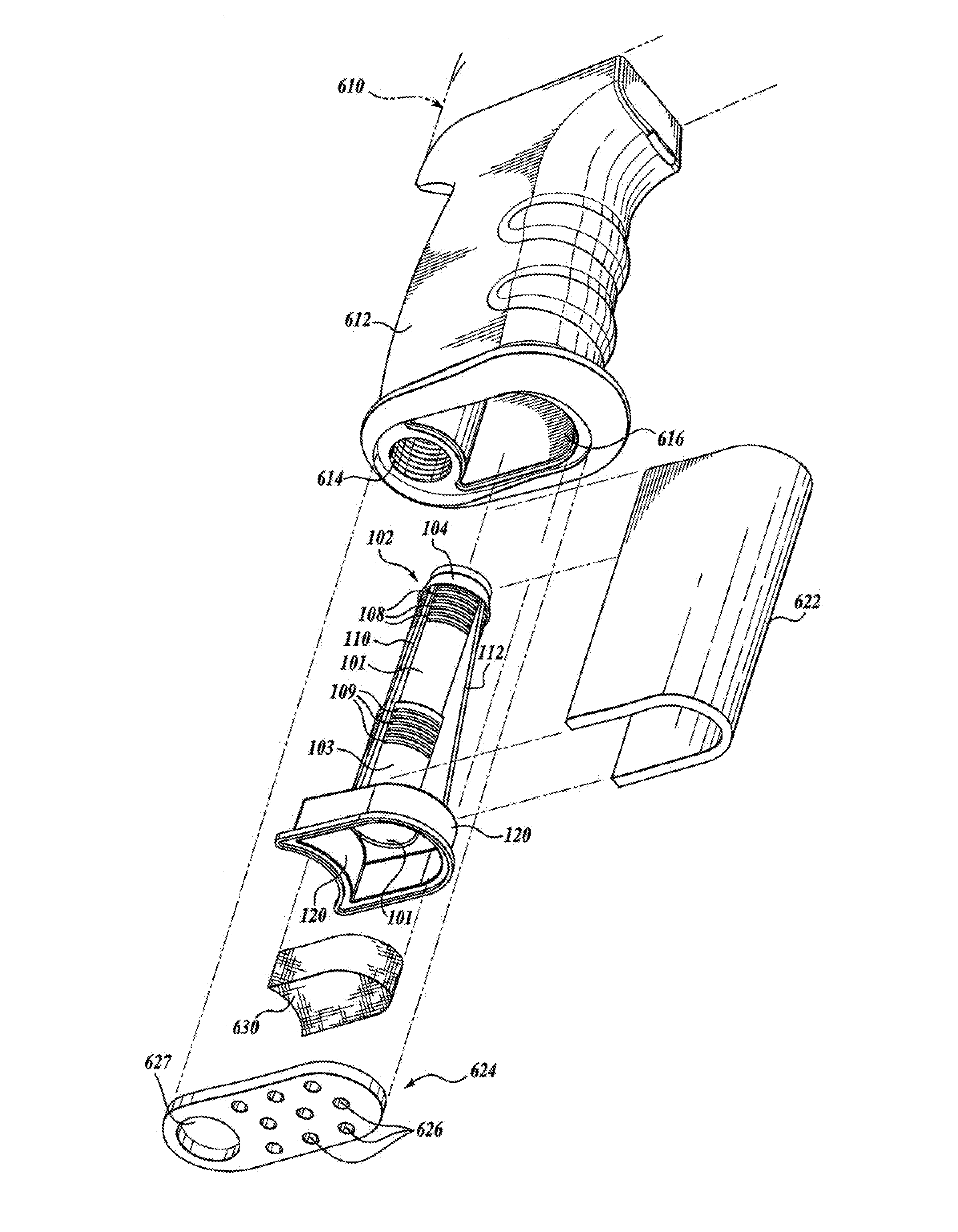
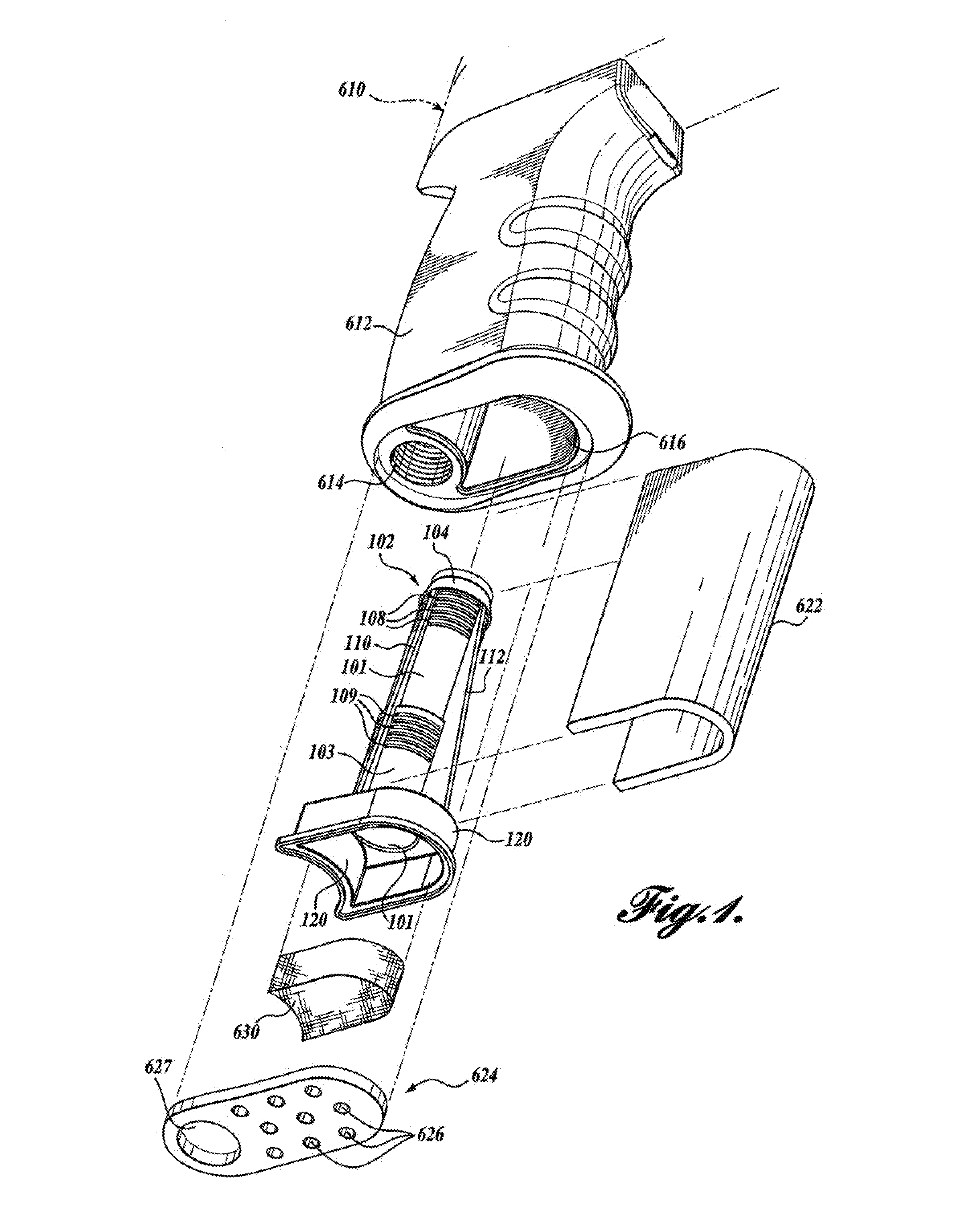
[0025]Referring initially to FIG. 8, a prior art muffler assembly 600 as disclosed in U.S. Pat. No. 7,216,739 (previously incorporated herein by reference) is shown in connection with a handle 612 of a power tool 610. The muffler assembly 600 includes a tube member 602 having an upper flange 604 that is configured to be slidably inserted into an exhaust passage 616 provided in the handle 612 of the power tool 610. A tubular portion 606 extends downwardly from the flange 604. The tubular portion 606 includes a number of apertures 608 distributed along its length. An oversized, downwardly opening receptacle 620 is disposed at the lower end of the tubular portion 606. The receptacle 620 is also configured to be slidably insertable into the exhaust passage 616, which is adjacent the inlet passage 614. A flexible filter panel 622 is generally wrapped about the tubular portion 606 of the tube member 602, and a diffuser panel 630 is inserted into the receptacle 620.

[0026]The upper flange 6...


PUM


Abstract

A muffler assembly for a pneumatic power tool includes a tube member defining an interior volume. The tube member includes an upper segment and a lower segment. The upper segment defines a first diameter and includes a closed upper end to inhibit fluid communication with the interior volume therethrough, a lower end, a first portion defining a plurality of vents to enable fluid communication with the interior volume therethrough, and a second portion defining a continuous surface to inhibit fluid communication with the interior volume therethrough. The lower segment defines a second diameter greater than the first diameter and includes an upper end in fluid communication with the lower end of the upper segment, a lower end, a first portion defining a plurality of vents to enable fluid communication with the interior volume therethrough, and a second portion defining a continuous surface to inhibit fluid communication with the interior volume therethrough.

Description

CROSS-REFERENCE TO RELATED APPLICATIONS[0001]This application claims the benefit of, and priority to, U.S. Provisional Patent Application No. 61 / 976,431, filed on Apr. 7, 2014, the entire contents of which are incorporated herein by reference.BACKGROUND[0002]Technical Field[0003]The present disclosure relates to power tools and, more particularly, to a muffler for a pneumatic power tool.[0004]Background of Related Art[0005]Pneumatic power tools, e.g., ratchets, drills, wrenches, grinders, sanders, and the like, are commonly used in industrial and residential settings. Such tools typically include a hollow handle defining a chamber that provides an inlet and exit conduit for the high pressure air that powers the tool motor. The chamber includes an air intake passage and an air exhaust passage. Each passage extends between the motor and an opening in or near the bottom surface of the handle. The portion of the intake passage located near the handle opening typically includes a standar...

Claims


Application Information

Patent Timeline
IPC IPC(8): B25F5/00G10K11/16
CPCG10K11/161B25F5/00B25D17/12F01N3/0212
Inventor STERLING, ROBERT E.
Owner EXHAUST TECH
Learn More