Auxiliary device for installing piston rings

Inactive Publication Date: 2017-02-02
CTI TRAFFIC INDUSTRIES CO LTD
View PDF31 Cites 0 Cited by
  • Summary
  • Abstract
  • Description
  • Claims
  • Application Information

AI Technical Summary

Benefits of technology

The present invention provides an auxiliary device for installing piston rings that can be used for pistons and piston rings of various sizes. The device uses a transmission device to automatically install a piston ring, increasing production efficiency and saving labor costs. The changing of the connecting rod and bracing structure is easy, allowing for easy replacement with different sizes of components according to the requirements of different pistons and piston rings. The device is easy to use and enhances the utilization benefit of the installation process.

Problems solved by technology

However, such installing method wastes working time, and easily deforms or fractures the piston ring due to emissness of the operating personnel, thus resulting in increasing of cost.

Method used


Image

  • Auxiliary device for installing piston rings
  • Auxiliary device for installing piston rings
  • Auxiliary device for installing piston rings

Examples


first embodiment

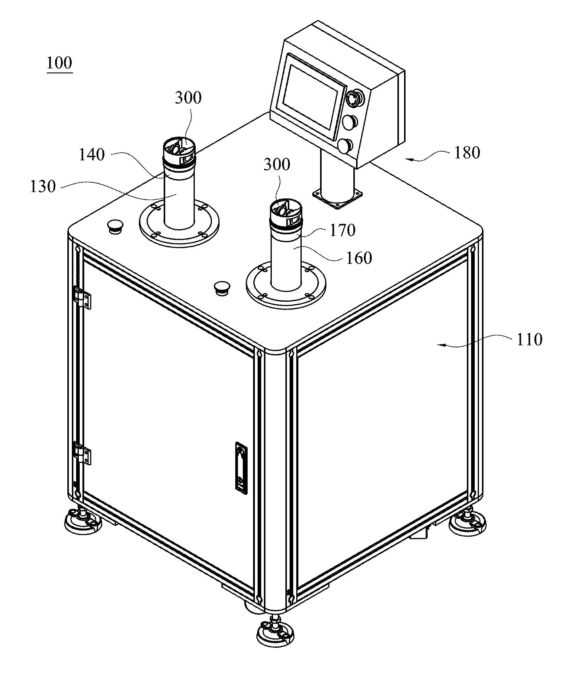
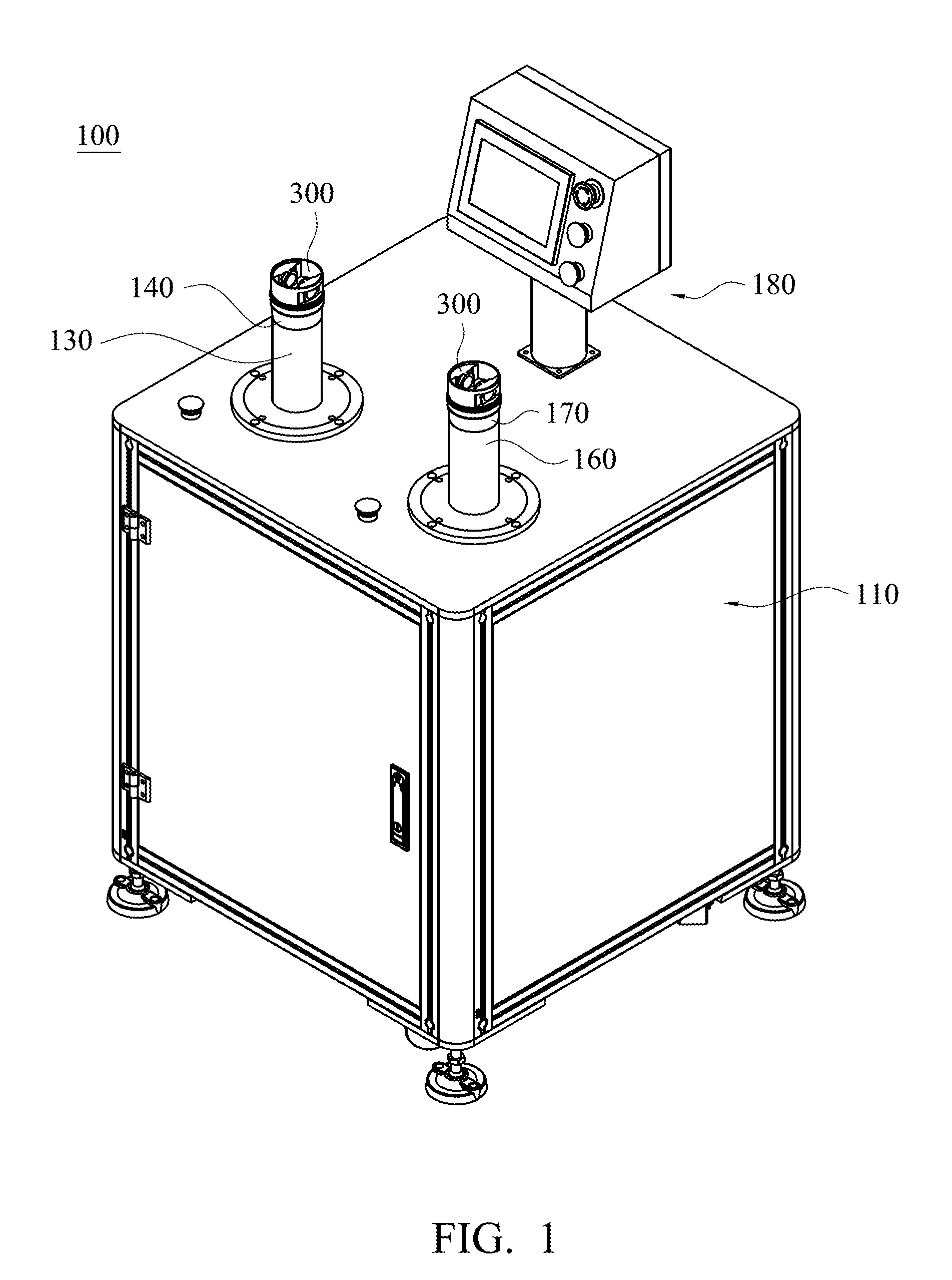
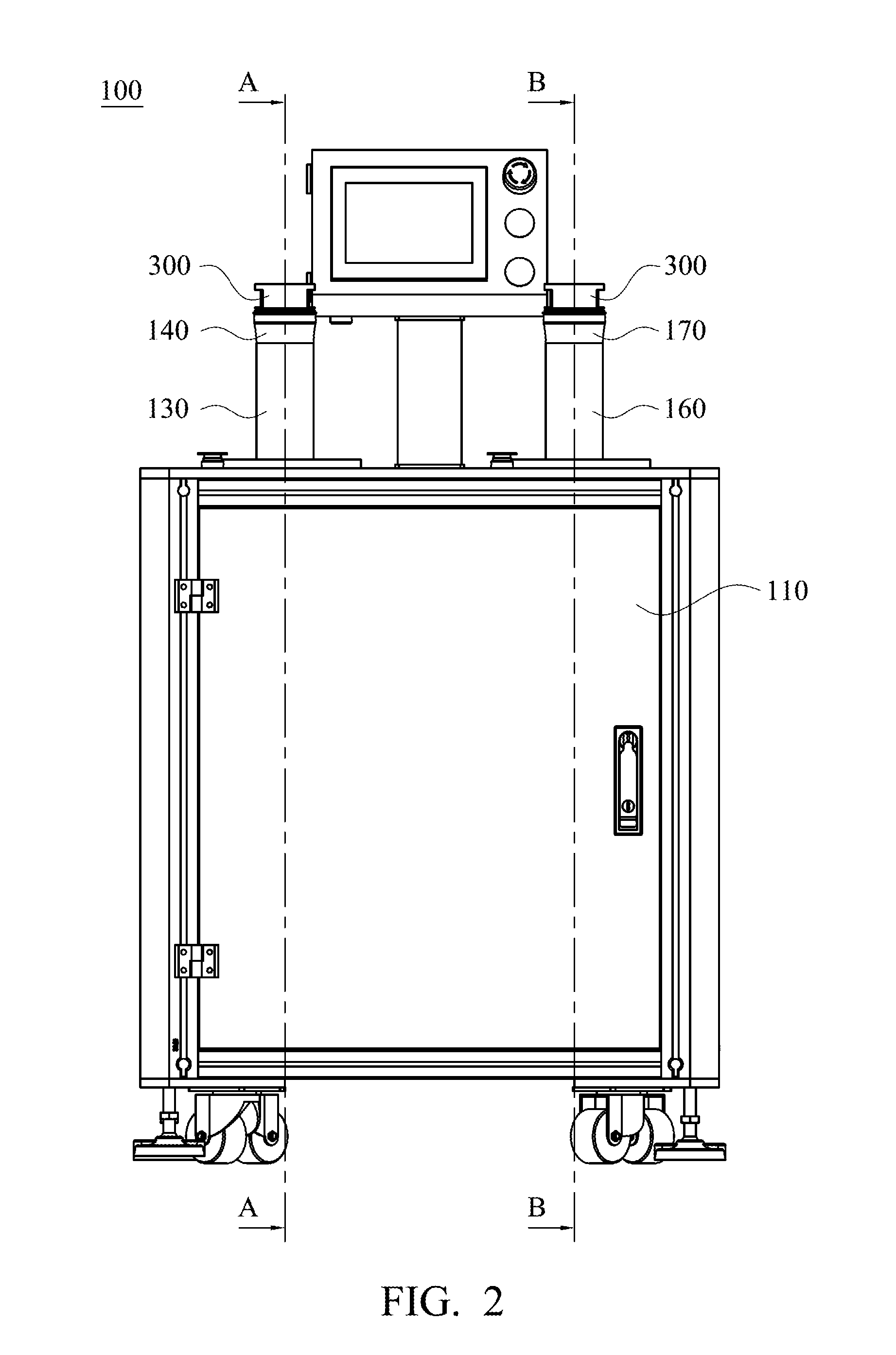
[0027]Referring to FIG. 1 and FIG. 2, FIG. 1 and FIG. 2 are respectively a schematic three-dimensional diagram and a schematic front view of an auxiliary device for installing piston rings in accordance with the present invention. An auxiliary device 100 for installing piston rings of the present embodiment is suitable for putting a piston ring 200 (shown in FIG. 4) around a piston 300. It is noted that, in order to illustrate a complete structure of the auxiliary device 100 for installing piston rings clearly and completely, the piston ring 200 is not shown in FIG. 1 and FIG. 2. A detail usage method of the auxiliary device 100 for installing piston rings will be described below.

[0028]Referring to FIG. 1, FIG. 2, FIG. 3A and FIG. 3B, in which FIG. 3A and FIG. 3B are schematic cross-sectional views taken along a line A-A and a line B-B in FIG. 2 respectively. The auxiliary device 100 for installing piston rings of the present embodiment mainly includes a mounting base 110, a first t...

second embodiment

[0039]It is noted that, the auxiliary device for installing piston rings of the present invention may have different structure designs. Referring to FIG. 5, FIG. 5 is a schematic three-dimensional diagram of an auxiliary device for installing piston rings in accordance with the present invention. A structure of an auxiliary device for installing piston rings 400 shown in FIG. 5 is substantially the same as that of the aforementioned auxiliary device for installing piston rings 100, and differences between the auxiliary device for installing piston rings 400 and the auxiliary device for installing piston rings 100 are that the auxiliary device for installing piston rings 400 only has a first transmission device 120, a first connecting rod 130 and a first bracing structure 140 as shown in FIG. 3A, and does not have a second transmission device 150, a second connecting rod 160 and a second bracing structure 170 as shown in FIG. 3B for meeting a use requirement of small-scale production...


PUM

PropertyMeasurementUnit
Diameteraaaaaaaaaa
Sizeaaaaaaaaaa

Abstract

An auxiliary device for installing piston rings is described, which includes a mounting base, a transmission device, a connecting rod and a bracing structure. The mounting base includes a platform, an opening hole and an accommodating space. The transmission device is disposed in the accommodating space and includes a guide screw rod, a sliding base and a motor. The sliding base is slidably screwed on the guide screw rod. The motor can drive the guide screw rod to move the sliding base. The connecting rod is disposed on the sliding base. An external diameter of the piston ring while being put around the connecting rod is greater than an inner diameter of the opening hole. The bracing structure is disposed on the connecting rod. An external diameter of the bracing structure is getting greater from one end connected to the connecting rod. The bracing structure can accommodate the piston.

Description

RELATED APPLICATIONS[0001]This application claims priority to Taiwan Application Serial Number 104124276, filed Jul. 27, 2015, which is herein incorporated by reference.BACKGROUND[0002]Field of Invention[0003]The present invention relates to an installing auxiliary device. More particularly, the present invention relates to an auxiliary device for installing piston rings.[0004]Description of Related Art[0005]Pistons are important elements in pneumatic systems or hydraulic systems. A piston ring is typically put around the piston. With the piston ring, the piston can be firmly fastened in a pneumatic cylinder or a hydraulic cylinder, thereby achieving a purpose of seal.[0006]A conventional method for installing a piston ring on a piston is manually operated by operating personnel. The operating personnel slowly embeds the piston ring into a groove on the piston by using manpower directly, so as to position the piston ring on the piston. However, such installing method wastes working ...

Claims


Application Information

Patent Timeline
IPC IPC(8): B23P15/08
CPCB23P15/08B23P19/088B23K37/0531B23K37/0538B23Q1/00B23Q1/03
Inventor LU, WAN-CHIEH
Owner CTI TRAFFIC INDUSTRIES CO LTD
Why Eureka
Try Eureka