Medical tubing and catheter control

a technology for medical tubing and catheter control, applied in the direction of catheters, etc., can solve the problems of increasing damaging the catheter as well as the patient's bladder and/or urethra, and reducing so as to reduce the discomfort and risk of infection, and increase the irritation on the penis tip

Active Publication Date: 2017-01-26
ENGELHARDT BERNARD
View PDF4 Cites 10 Cited by
  • Summary
  • Abstract
  • Description
  • Claims
  • Application Information

AI Technical Summary

Benefits of technology

This patent describes a way to prevent discomfort and infection caused by a foleys catheter. A controlling device is needed to compensate for changes in the length of the drainage tube path, which can occur when the catheter moves in relation to the patient. This device should provide a minimal pull on the catheter, reducing the chance of damage to the bladder and ureter. The method is non-invasive and low cost, potentially saving millions of dollars per year in hospital treatment costs.

Problems solved by technology

The free loop can also get caught on clothing resulting in a substantial pull on the catheter, which can damage the catheter as well as the patient's bladder and / or urethra.
All of these movements further increase the irritation on the penis tip.

Method used


Image

  • Medical tubing and catheter control
  • Medical tubing and catheter control
  • Medical tubing and catheter control

Examples


first embodiment

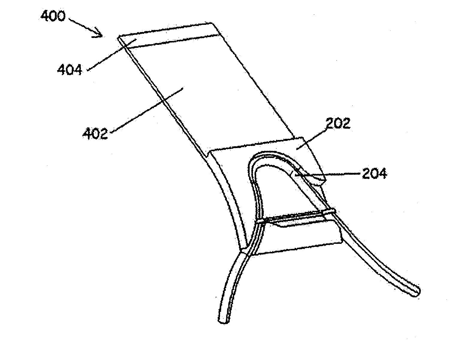
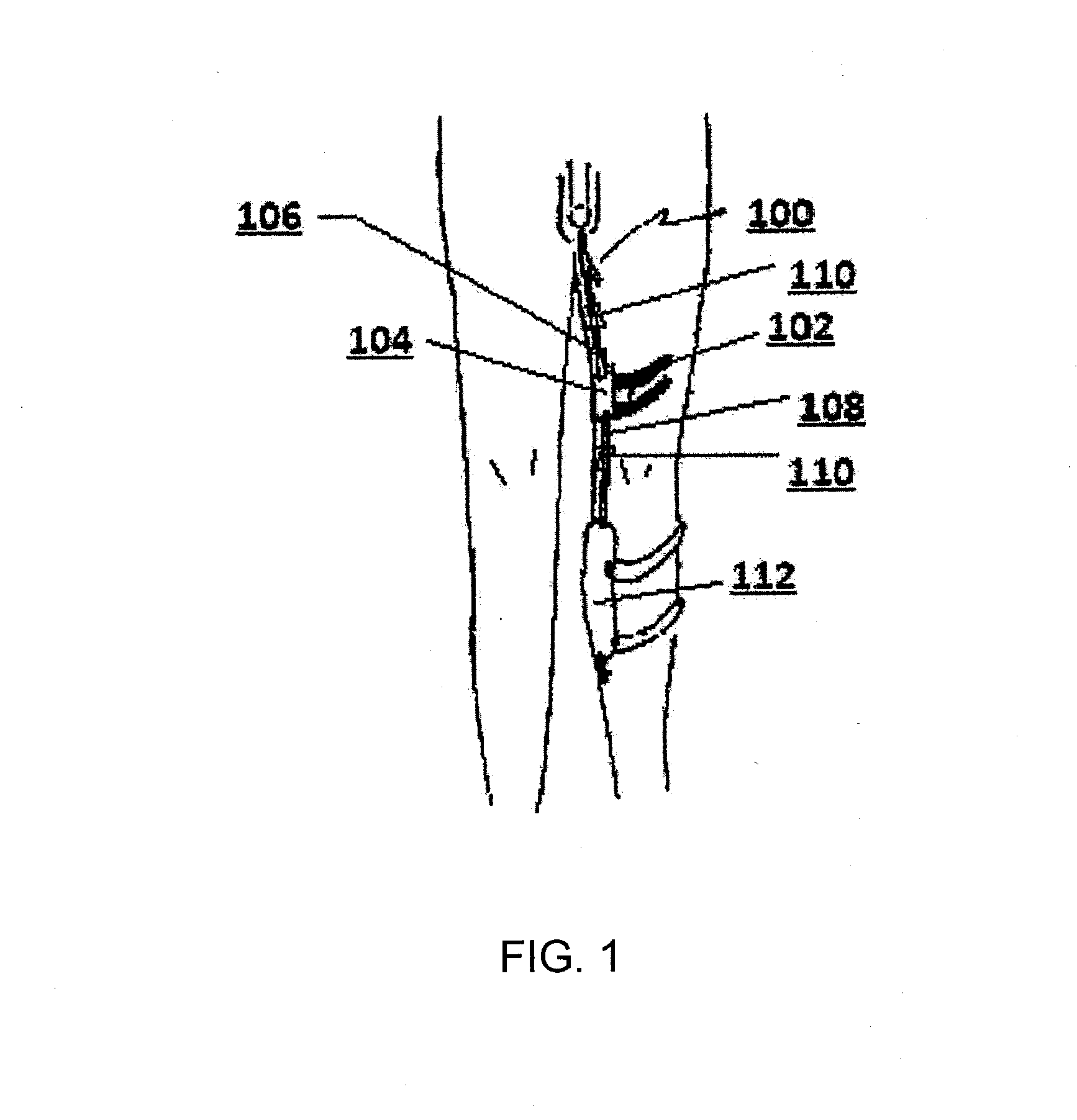
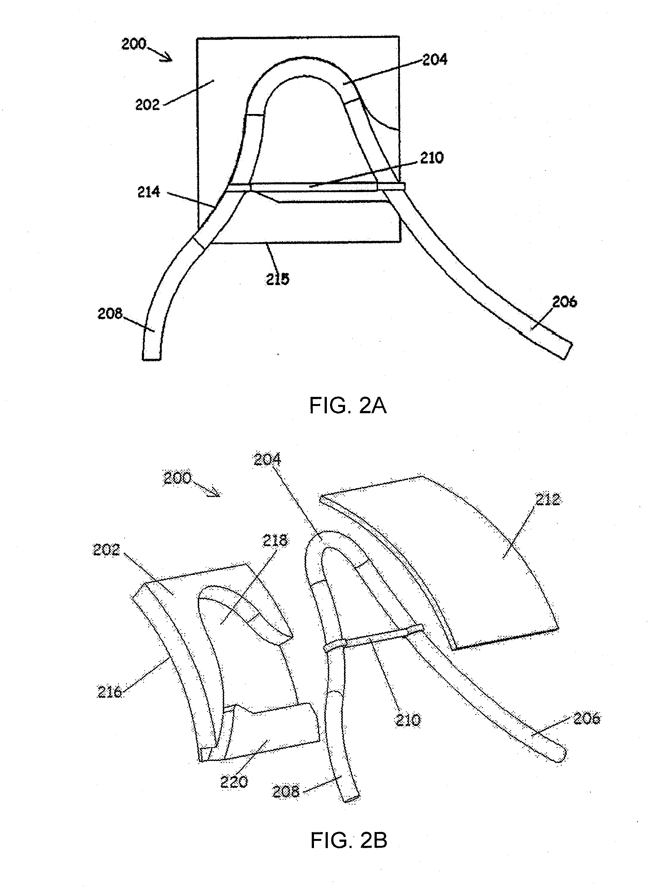
[0132]The catheter controller 200, is attached to the patients leg by means of an adhesive surface 216 on the backside of the base 202 (FIG. 2B). It is orientated such that the end of the drainage (or outgoing) tube 208 points in the general direction of the drainage bag, where it will then be connected. As can be seen by FIG. 2A, the outgoing tube 208 is attached to the base 202 and positioned approximately 45.degree. relative to the bottom edge 215 of the base 202. The 45.degree. angle of the outgoing tube 208 optimally places the outgoing tube 208 such that the maximum amount of bend the outgoing tube 208 will have to undergo is about 45.degree. regardless of the patient's leg position. The incoming tube 206 is connected to the external end of the Foley catheter 100 and is held in constant tension by the tension spring 210, when placed in between the calibration markings 302 shown in FIG. 3A (see method of operation for securing controller below). Shown in FIGS. 3A and 3B, the li...


PUM


Abstract

One embodiment is an improved method for providing a tube for attachment to a medical device such as a catheter that provides for intermittent changes in tube path length as a result of body movement thereby reducing the stress and pain caused by pulling on the device, as well as the optional provision to provide a very low, controlled tension that provides improved stability of the medical device without damage to the surrounding body tissues. This controlled tension can be applied or removed intermittently by a medical practitioner or the patient. The tubal devices shown in Fig and Fig both provide for extension in tubal path length while simultaneously providing for intermittent or continuous low tension pull on the catheter. Provision is also made for a continuous smooth fluid path with no moving internal parts.

Description

CROSS-REFERENCE TO RELATED APPLICATIONS[0001]This application claims the benefit of U.S. provisional patent application No. 61 / 359,912 filed Jun. 30, 2010 and U.S. provisional patent application No. 61 / 478,566 filed Apr. 25, 2011.BACKGROUND[0002]1. Field of Invention[0003]This invention relates to fluid handling lines and their attachment to catheters or other medical devices, more specifically to tube length compensation features that help to stabilize and isolate the catheter or other medical devices.[0004]2. Prior Art[0005]There are many areas in the medical field where a fluid handling tube is attached to a device fastened onto or into the body. Problems arise that are the result of body movements that alter the length of the tubal path, instances where the tube is subjected to sudden hard tugs, and movement of the device itself as a result of skin movement even when fastened down with adhesive tape. In cases where the device is a catheter, whether urinary, IV, or other, the mov...

Claims


Application Information

Patent Timeline
Patent Type & Authority Applications(United States)
IPC IPC(8): A61M25/02
CPCA61M25/02A61M2025/0266A61M2025/024
Inventor ENGELHARDT, BERNARD
Owner ENGELHARDT BERNARD
Why Eureka
Try Eureka