
Distributed playback architecture

a playback architecture and master element technology, applied in the direction of selective content distribution, electrical equipment,pictoral communication, etc., can solve the problems of not being able to transmit multimedia content in an uncompressed format, being annoyant to spectators, and relatively low network bandwidth

Active Publication Date: 2017-01-05
CINEMO
View PDF3 Cites 0 Cited by
  • Summary
  • Abstract
  • Description
  • Claims
  • Application Information

AI Technical Summary

Benefits of technology

The patent text describes a master element and several slave elements in a distributed playback system. The master element sends beacon packets to the slave elements to synchronize playback. The master element also has a response packet evaluator to determine network latency between the master element and the slave elements and adjust the transmission of payload data packets accordingly. The master element also has an arbitrator to resolve conflicts between playback control commands and ensure safety by ignoring certain slave elements based on their status. The slave element also has a user interface for user input regarding playback control. Overall, the system is transparent to the network and allows for seamless playback control across slave elements.

Problems solved by technology

The bandwidth of the network is considered to be relatively low when it would be insufficient for transmitting the entire amount of data that shall ultimately be presented at the various terminals.
In other words, while the network bandwidth may well be sufficient for transmitting the multimedia content in a compressed format, it may not be sufficient for transmitting the multimedia content in an uncompressed format (e.g. data in a video interface standard such as DVI).
In the opposite case, however, when video lags behind the audio signal—it is typically annoying to the spectator for values between 5 and 10 ms and up.
Especially in connection with video content having frequent changes between brighter scenes and darker scenes, even a small temporal offset between the two or more display devices may be disturbing to the spectators.

Method used


Image

  • Distributed playback architecture
  • Distributed playback architecture
  • Distributed playback architecture

Examples


Embodiment Construction

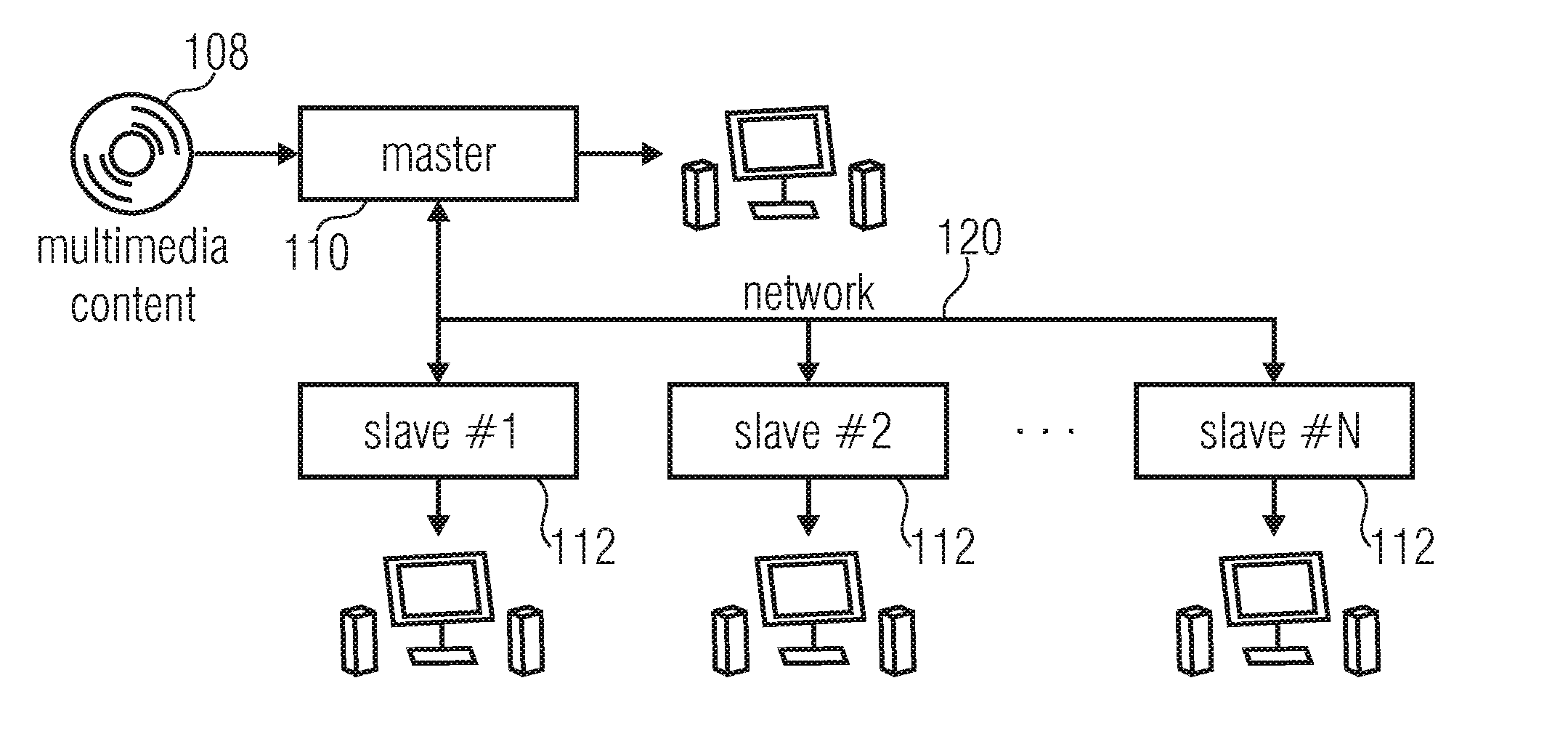
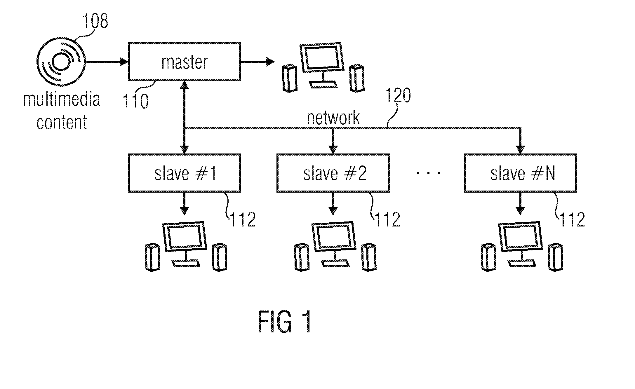
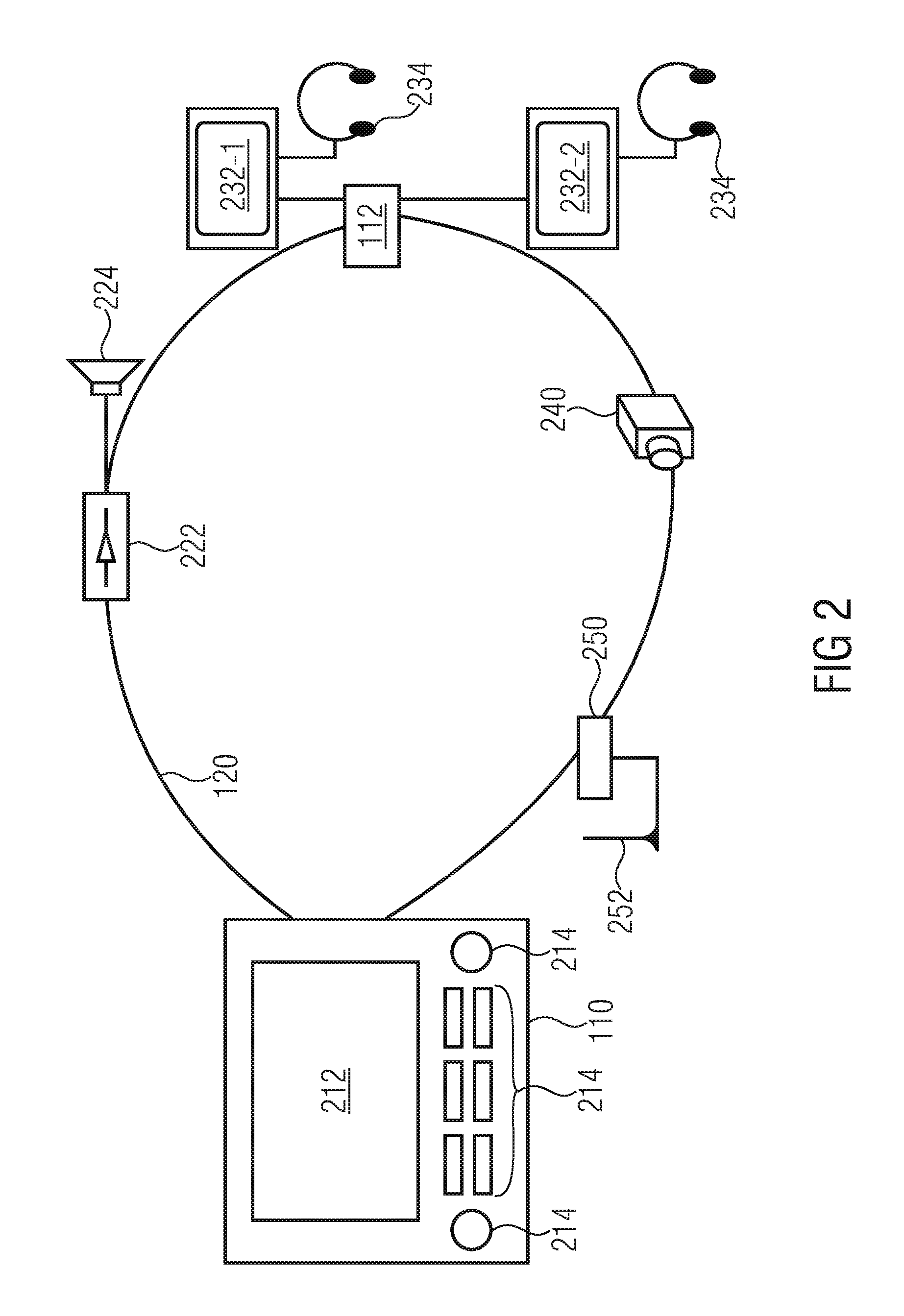
[0053]FIGS. 1 and 2, which have already been described above, show a schematic block diagram of a distributed playback architecture and a typical configuration of a distributed entertainment system as it may be found in automobiles.

[0054]FIG. 3 shows a schematic datastream 300, the main function of which is to transmit information from a media source or media origin to a media consumer connected to each other via a network, a bus system, or the like. The datastream 300 comprises a plurality of payload packets P0 to P8. In FIG. 3, the datastream or packet stream 300 is represented with no pauses between the packets, i.e. a subsequent packet immediately follows a preceding packet. In the alternative, the datastream 300 could present a sporadic transmission pattern, that is, there may be a temporal gap between the preceding packet and the subsequent packet.

[0055]In the context of a distributed playback architecture for media data, the media data is transmitted within the datastream 300...


PUM


Abstract

Master element for a distributed playback architecture for a media data, having: a payload data source for providing payload data packets; a beacon packet creator for creating beacon packets useable for synchronizing a playback process of the payload data packets at, at least one, slave element in the distributed playback architecture; and a network interface for transmitting an interleaved packet stream to the at least one slave element, the interleaved packet stream having the payload data packets provided by the payload data source and the beacon packets created by the beacon packet creator. A corresponding slave element, the distributed playback architecture, a method, and a computer program product are also disclosed.

Description

CROSS-REFERENCE TO RELATED APPLICATIONS[0001]This application is a continuation of copending U.S. patent application Ser. No. 13 / 861,669, filed Apr. 12, 2013, which is a continuation of International Application No. PCT / EP2011 / 064218, filed Aug. 18, 2011, and additionally claims priority from US Application No. 61 / 393,570 filed Oct. 15, 2010, all of which are incorporated herein by reference in their entirety.BACKGROUND OF THE INVENTION[0002]The field of the present invention is related to systems and methods for playing back media data, and in particular to a master element for a distributed playback architecture, a slave element for the distributed playback architecture, a method for a synchronized playback in the distributed playback architecture and a computer readable digital storage medium usable for causing a processor to perform the method for synchronized playback.[0003]Distributed playback enables the synchronized presentation and interactive control of linear multimedia c...

Claims


Application Information

Patent Timeline
Patent Type & Authority Applications(United States)
IPC IPC(8): H04N21/6332H04N21/442H04N21/43H04N21/436H04N21/41H04N21/414
CPCH04N21/4122H04N21/41407H04N21/4305H04N21/43615H04N21/44227H04N21/43072H04N21/6332
Inventor RUSSELL, IVAN
Owner CINEMO
Learn More