System for measuring air mass flow into a gas turbine

a gas turbine and air mass flow technology, which is applied in the direction of liquid fuel engines, combustion-air/fuel-air treatment, and separate processes, etc., can solve the problems of inability to accurately measure the quantity, significantly reduce the power produced by the engine, and other techniques have proven extremely expensive, inaccurate, or accura

Inactive Publication Date: 2017-01-05
SIEMENS ENERGY INC
View PDF8 Cites 10 Cited by
  • Summary
  • Abstract
  • Description
  • Claims
  • Application Information

AI Technical Summary

Benefits of technology

This patent describes a method and system for measuring the air mass flow into a compressor section in a gas turbine engine. The system includes a chamber with multiple filter packages, each containing a flow sensor and a filter structure. The filters filter the air before it passes through the chamber, and the flow sensors measure the velocity of the air as it passes through the corresponding filter package. These measurements, combined with data from temperature, humidity, and static pressure sensors, are used to characterize the air mass flow and density fields in two dimensions. Overall, the system allows for accurate and detailed measurement of the air mass flow into the compressor section of a gas turbine engine.

Problems solved by technology

This quantity is difficult to measure accurately because the most accurate measurement methods themselves create an impedance to air flow, which significantly reduces the power produced by the engine.
Other techniques have proven extremely expensive, inaccurate, or accurate but requiring a large configuration space.
However, using a flow nozzle requires ample space to accommodate its setup requirements and is very expensive.
Additionally, the relatively high pressure drop across the flow nozzle reduces the power output of the engine.
While the estimate is fairly accurate when used for high load operation, it not consistently accurate under all load conditions.
Additionally, this method only gives a mass flow estimate for performance evaluation and is not useful for monitoring the flow distribution in the air intake.
Thus, it cannot be used to optimize the flow performance of the air intake locally.

Method used


Image

  • System for measuring air mass flow into a gas turbine
  • System for measuring air mass flow into a gas turbine
  • System for measuring air mass flow into a gas turbine

Examples


Embodiment Construction

[0020]To facilitate an understanding of embodiments, principles, and features of the present disclosure, they are explained hereinafter with reference to implementation in illustrative embodiments. Embodiments of the present disclosure, however, are not limited to use in the described systems or methods.

[0021]The components and materials described hereinafter as making up the various embodiments are intended to be illustrative and not restrictive. Many suitable components and materials that would perform the same or a similar function as the materials described herein are intended to be embraced within the scope of embodiments of the present disclosure.

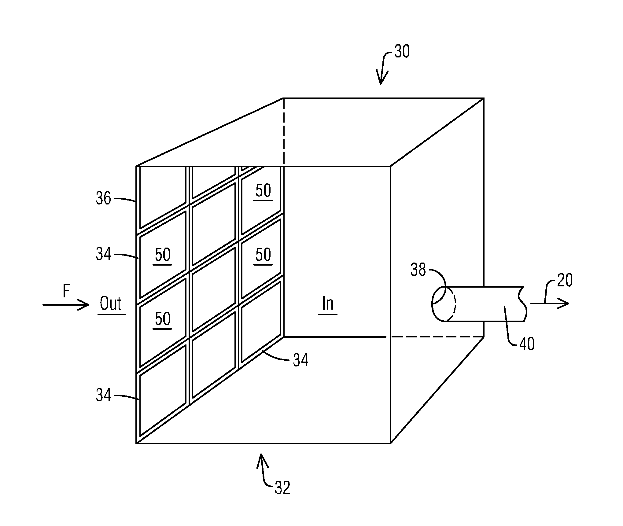
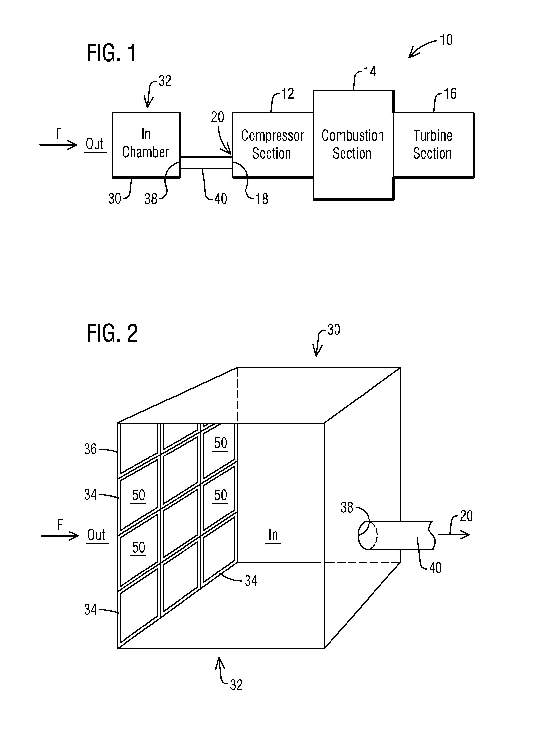
[0022]Within the air intake installation into the gas turbine, two of the types of filter structures may be used for filtering the air going into the compressor section are described below. Flat static rectangular filters are typically installed in the air intake installation in a grid-like pattern such that the filters are parallel a...


PUM

PropertyMeasurementUnit
Temperatureaaaaaaaaaa
Pressureaaaaaaaaaa
Flow rateaaaaaaaaaa

Abstract

A method for measuring air mass flow into a compressor section of a gas turbine engine is provided. Air is introduced into a chamber upstream from an inlet of the compressor section. The chamber includes filter packages with at least some of the filter packages including a flow sensor and a filter structure, the filter structure filtering the air. The flow sensors measure the velocity of the air flowing through the corresponding filter package. A controller uses the air flow sensor signal data to characterize a two dimensional flow field through the chamber. Additionally, a plurality of temperature, humidity, and static pressure sensors are disposed throughout the filter packages. The controller uses the temperature, humidity, and static pressure sensor signal data to characterize a two dimensional density field through the chamber. The controller combines the flow field with the density field to calculate a two dimensional air mass flow field.

Description

CROSS-REFERENCE TO RELATED APPLICATIONS[0001]This application is a continuation in part of PCT Application Serial No. PCT / US2014 / 031013, titled, System and Method for Monitoring Air Flow into a Turbine Engine, filed Mar. 18, 2014 and as such claims the benefit of its priority date which is hereby incorporated by reference.BACKGROUND[0002]1. Field[0003]The present disclosure relates generally to a method and system for measuring the air mass flow into an inlet of a compressor section of a gas turbine engine, and more particularly, to a method and system for measuring the total air mass flow into the inlet of a compressor section of a gas turbine engine.[0004]2. Description of the Related Art[0005]In a turbomachine, such as a gas turbine engine, air is pressurized in a compressor section then mixed with fuel and burned in a combustion section to generate hot combustion gases. The hot combustion gases are expanded within a turbine section of the engine where energy is extracted from th...

Claims


Application Information

Patent Timeline
IPC IPC(8): F04D27/00G01F1/76G01M15/14F04D29/70F04D29/54
CPCF05D2270/3061F05D2270/80B01D46/0086B01D46/444F02C7/055F02C7/057F02C9/00F05D2240/12F05D2260/607F05D2260/80F02M35/0201G01F1/86G01F1/88F02M35/0215F05B2220/302B01D46/58B01D46/62F04D27/001F04D29/545F04D29/701G01F1/76G01M15/14
Inventor CLAUSSEN, HEIKOMCCONKEY, JOSHUA S.BUNCE, RICHARD H.
Owner SIEMENS ENERGY INC
Why Eureka
Try Eureka