
Display indicating aiming point relative to target size indicator

a technology of display and target size, applied in the field of display, can solve the problems of repeating the process, missing the shot altogether, interfering with the trajectory of the projectile, etc., and achieve the effect of improving the display of line of sight distance and horizontal distan

Active Publication Date: 2016-12-29
EVRIO
View PDF9 Cites 8 Cited by
  • Summary
  • Abstract
  • Description
  • Claims
  • Application Information

AI Technical Summary

Benefits of technology

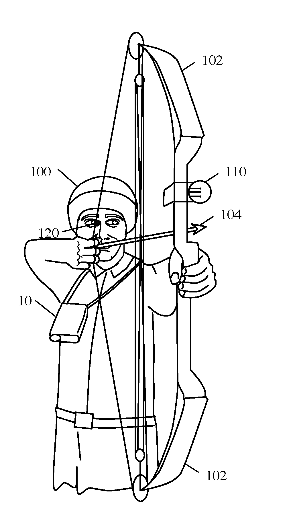
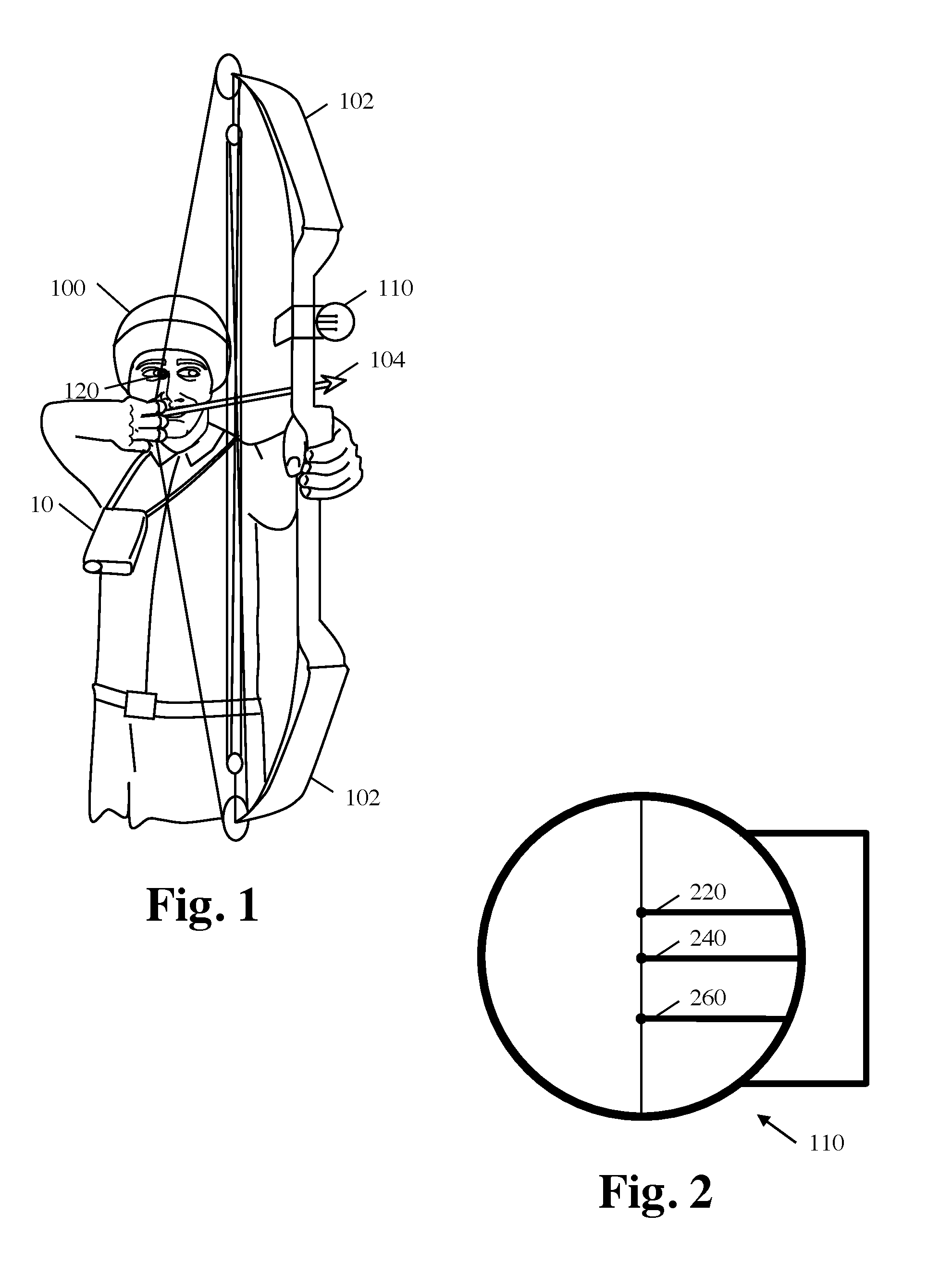
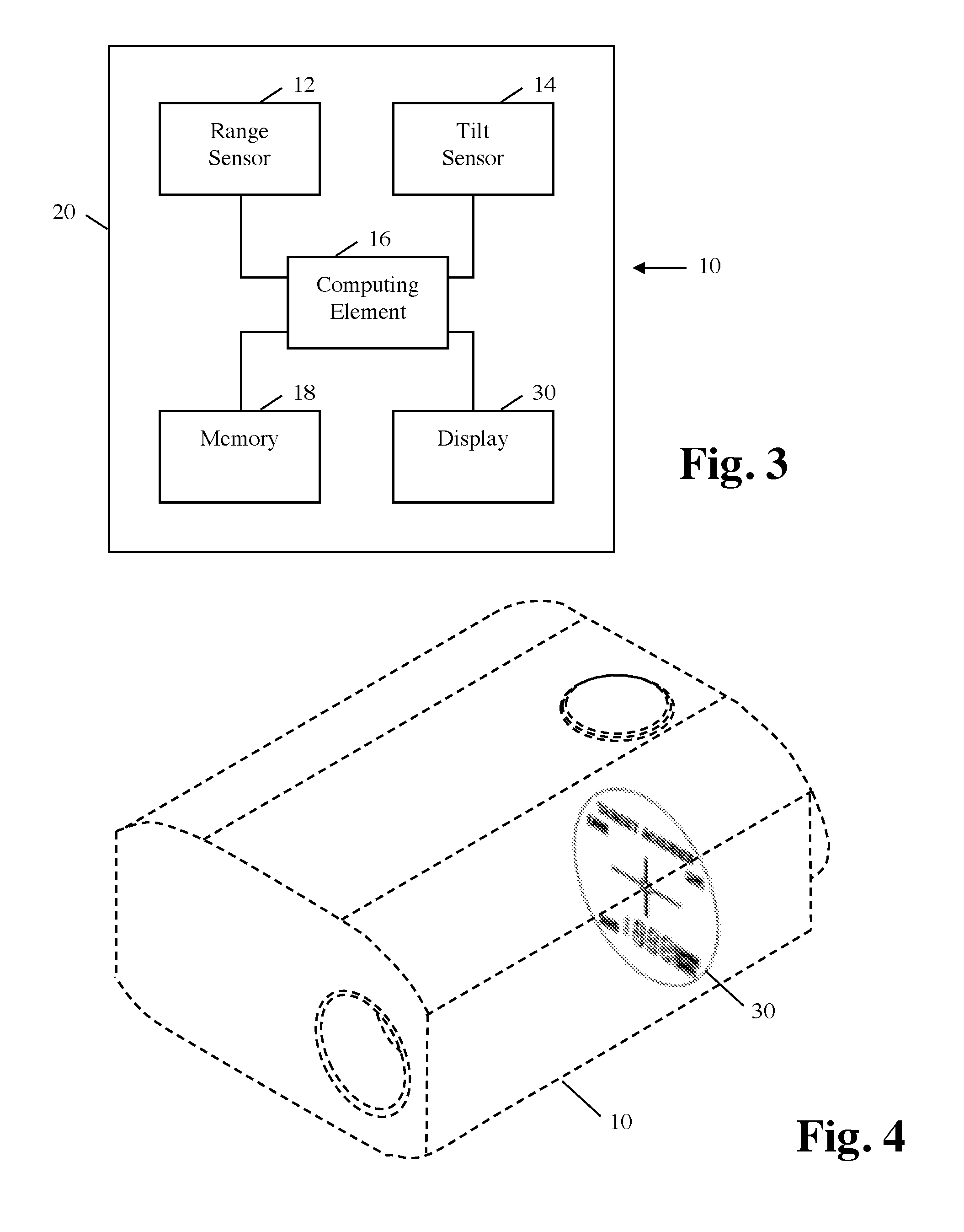
The present invention provides a display for a rangefinder device that shows information about a projectile's trajectory, allowing the user to determine if there is a clear shot. The display can automatically scan the points along the projectile's trajectory and provide indicators to the user. The display can also dynamically indicate the presence of obstacles in the projectile's trajectory and provide an aiming point for the user. The invention also includes a lightweight rangefinder comprising a high-resolution display and a digital camera. The technical effects of the invention include improved accuracy and safety in firearm and bow use.

Problems solved by technology

In the field there may be obstacles such as tree branches, bushes, and other wildlife which are not the target and which may interfere with the trajectory of the projectile.
All of the movement and time taken during these steps will likely be noticed by the target and allow the target an opportunity to move resulting in having to repeat the process or miss the shot altogether.

Method used


Image

  • Display indicating aiming point relative to target size indicator
  • Display indicating aiming point relative to target size indicator
  • Display indicating aiming point relative to target size indicator

Examples


Embodiment Construction

[0121]The following detailed description of the invention references the accompanying drawings that illustrate specific embodiments in which the invention can be practiced. The embodiments are intended to describe aspects of the invention in sufficient detail to enable those skilled in the art to practice the invention. Other embodiments can be utilized and changes can be made without departing from the scope of the present invention. The following detailed description is, therefore, not to be taken in a limiting sense. The scope of the present invention is defined only by the appended claims, along with the full scope of equivalents to which such claims are entitled.

Projectile Trajectories

[0122]FIG. 7A is a diagram illustrating a first range to a target T and an associated projectile trajectory 2. The rangefinder device 10 is show level such and the associated projectile trajectory leaves the weapon and enters the target at substantially the same true elevation (horizontal line 4)....


PUM


Abstract

An improved display provides information regarding a projectile trajectory so that a user is informed whether or not there is a clear shot. In some embodiments, an intermediate point in the projectile trajectory is an aiming point and is indicated in relation to the visualized target or target reference. The rangefinder device is calibrated to a weapon having a sight, for example, having a riflescope calibrated at 100 yards. The aiming point is displayed showing the intermediate point in the projectile trajectory that corresponds with riflescope cross hairs at a predetermined zero setting. The user places the riflescope cross hairs on the point visualized in the rangefinder device. Alternatively, the aiming point is displayed relative to the magnified image of the target, a generic reference image, or a user selectable reference images.

Description

RELATED APPLICATIONS[0001]This application is a continuation in part of U.S. patent application Ser. No. 12 / 859,769 filed Aug. 19, 2010, which issued as U.S. Pat. No. 8,282,493 on Oct. 9, 2012. U.S. patent application Ser. No. 13 / 599,450, filed Aug. 30, 2012, issued as U.S. Pat. No. 8,500,563 on Aug. 6, 2013, is a continuation of U.S. patent application Ser. No. 12 / 859,769. U.S. patent application Ser. No. 13 / 959,655, filed Aug. 5, 2013, is also a continuation of U.S. patent application Ser. No. 12 / 859,769 and U.S. patent application Ser. No. 13 / 599,450, and is pending. U.S. patent application Ser. No. 14 / 458,946, filed Aug. 13, 2014, is also a continuation of U.S. patent application Ser. Nos. 12 / 859,769; 13 / 599,450; and Ser. No. 13 / 959,655, and is pending. U.S. patent application Ser. No. 14 / 471,786, filed Aug. 28, 2014, is also a continuation in part of U.S. patent application Ser. Nos. 12 / 859,769; 13 / 599,450; 13 / 959,655; and Ser. No. 14 / 458,946, and is pending. This application c...

Claims


Application Information

Patent Timeline
Patent Type & Authority Applications(United States)
IPC IPC(8): F41G1/473F41G3/08F41G3/06F41G1/467F41G3/16
CPCF41G1/473F41G1/467F41G3/08F41G3/06F41G3/165F41G3/142
Inventor ROMAN, KENDYL A.LIVACICH, JOHN
Owner EVRIO
Learn More