
Contact Mechanic Tests using Stylus Alignment to Probe Material Properties

a contact mechanic and material technology, applied in the field of contact mechanics, can solve the problems of inability to reliably measure mechanical properties, limited scope of current industrial non-destructive techniques for mechanical properties, and equipment providing a hardness value which is not reliabl

Active Publication Date: 2016-12-22
MASSACHUSETTS MATERIALS TECH
View PDF3 Cites 4 Cited by
  • Summary
  • Abstract
  • Description
  • Claims
  • Application Information

AI Technical Summary

Benefits of technology

The patent text is about a "yoke" that connects the parts of a device and carries the forces and displacements from the main mechanism to the core of the device without affecting its normal operation. The technical effect of this is that it allows for smoother and more efficient functioning of the device.

Problems solved by technology

These events still occur too frequently in our society.
Current industrial non-destructive techniques for mechanical properties can be limited in scope to measuring the hardness of a material by indentation, which provides an index of a material's resistance to penetration by a hard indentor or stylus.
Although indentation testing is widely used, the traditional equipment provides a hardness value which is not a reliable measure of mechanical properties such as yield strength or ultimate strength, and provides no measure of ductility.
Therefore, these series of indents have limitations with respect to the study of microstructural gradients, such as changes in properties through welds and surface modifications.
This testing method is described in U.S. patent application Ser. No. 10 / 362,605, and is limited to select applications where materials utilize thin-films or coatings.
This restriction makes the technology unsuited for assessing mechanical properties of common engineering materials.
All of these contact mechanics methods utilize existing laboratory testing devices and systems, but the underlying test apparatus is either too complex or not sufficiently accurate for broad commercial use.
As a result, existing testing systems provide only partial solutions for evaluating mechanical properties.
As a result, the devices must be connected and disconnected for each individual test location, or alignment of the devices is not maintained.
Furthermore, these indentation testers provide limited information about the ductility of the material, especially within the heat affected zone of welded joints.
Indentation testing also typically provides limited information with respect to the cracking resistance and toughness of the material under service conditions.
There are currently no existing methods to systematically account for these gradients in mechanical properties, and therefore contact mechanics tests are only applicable for the small volume of material that is directly probed.

Method used


Image

  • Contact Mechanic Tests using Stylus Alignment to Probe Material Properties
  • Contact Mechanic Tests using Stylus Alignment to Probe Material Properties
  • Contact Mechanic Tests using Stylus Alignment to Probe Material Properties

Examples


Embodiment Construction

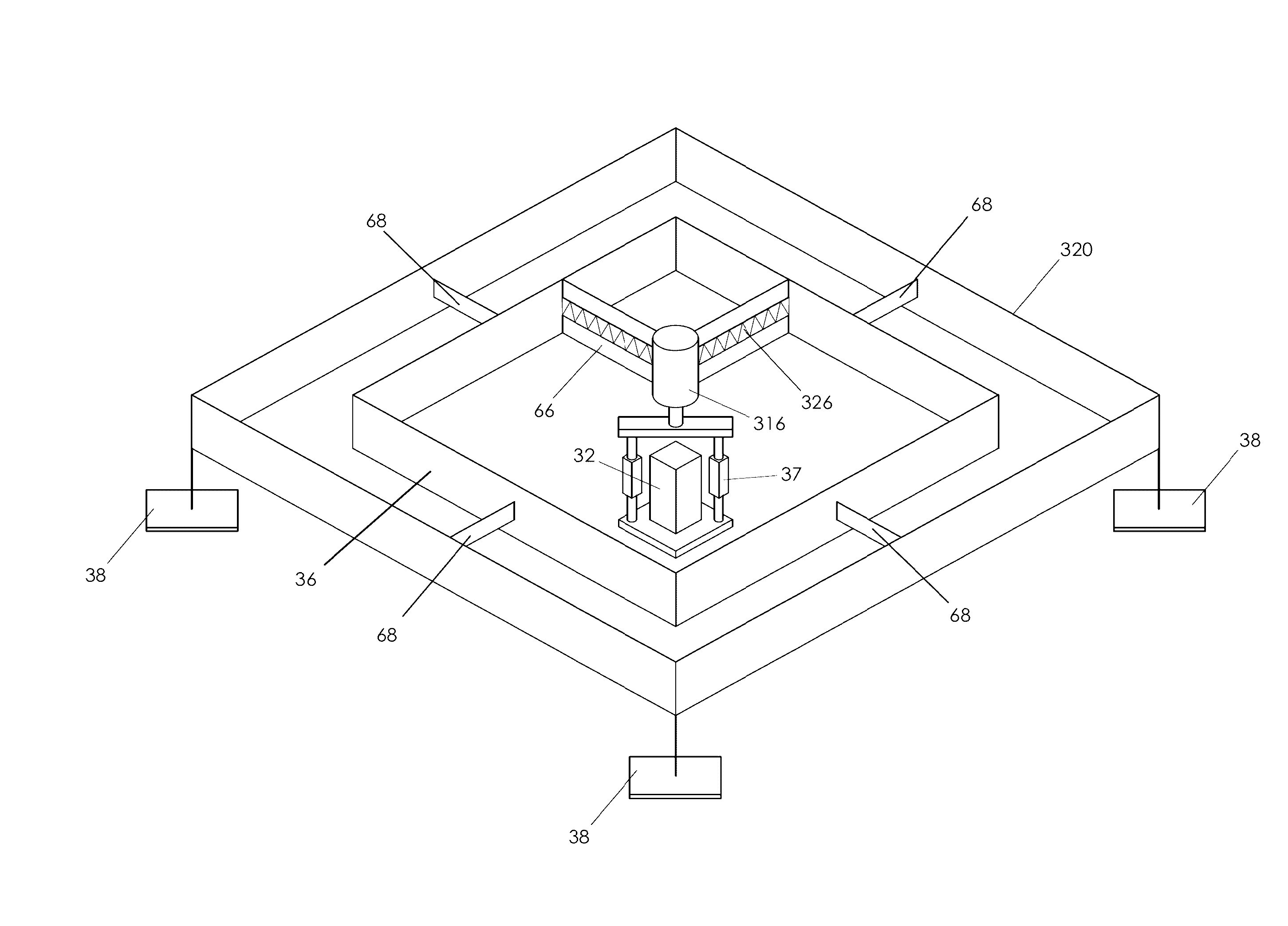
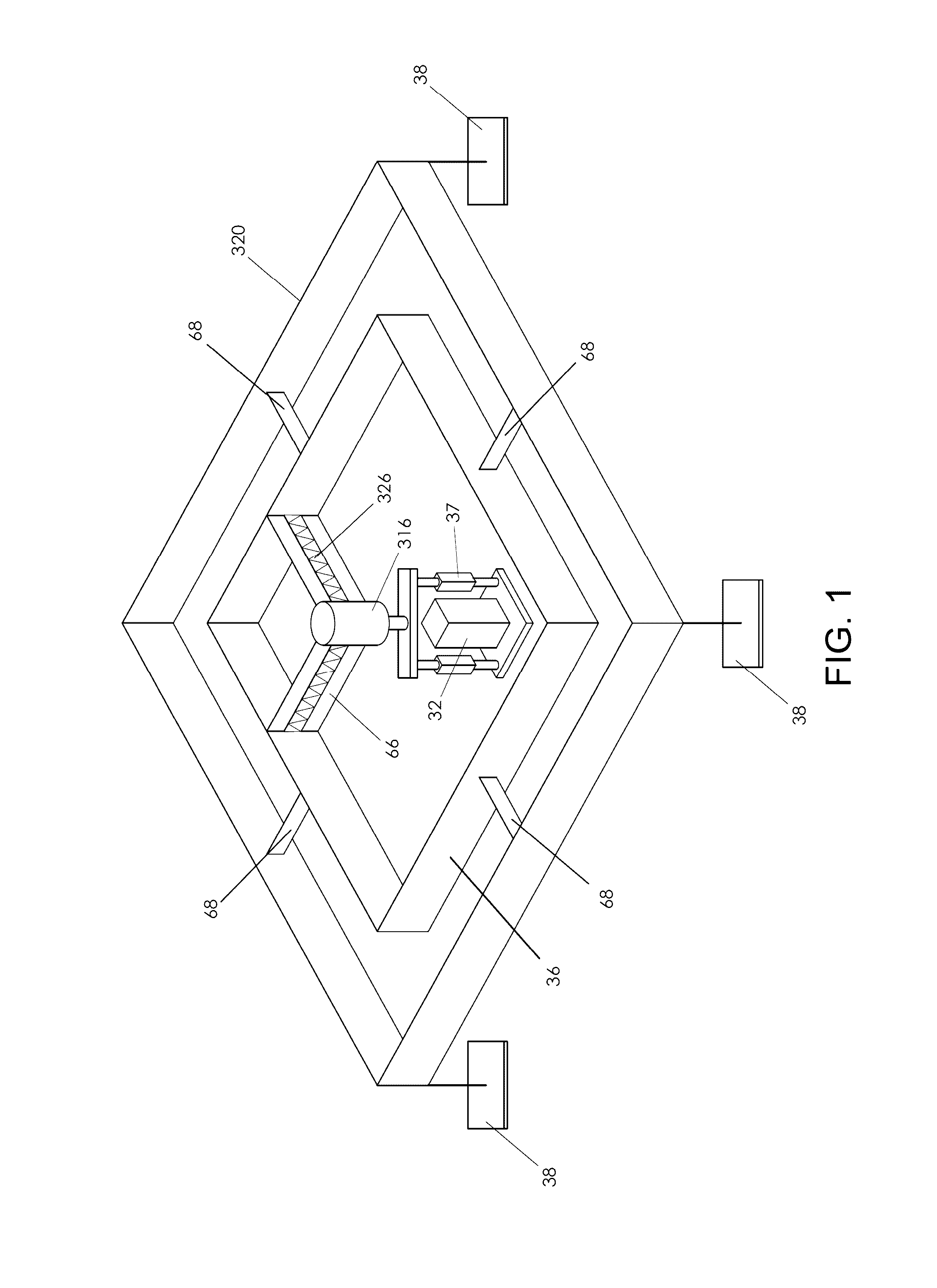
[0011]In one embodiment of the invention, an apparatus for performing a contact mechanics test on a substrate, the apparatus comprising (i) a stylus having a principal axis and shaped to deform the substrate at a stylus contact location, (ii) a core, in which the stylus is hosted, configured to engage the stylus against the substrate, (iii) a stylus engagement mechanism, coupled to the core or the stylus, configured to induce a contact load or a penetration depth to the stylus, (iv) a core engagement mechanism, coupled to the core, configured to maintain contact of the core and to move the core along the substrate surface, (v) a frame, in which the core engagement mechanism is hosted, configured to be fixed with respect to the apparatus or to be moved together with the core engagement mechanism as an assembly, (vi) a frame engagement mechanism configured to engage the frame with the substrate surface, and (vii) a substrate monitoring device configured to measure characteristics of s...


PUM

PropertyMeasurementUnit
included angleaaaaaaaaaa

Abstract

An apparatus for performing a contact mechanics test on a substrate includes a stylus, a core configured to engage the stylus against the substrate, a stylus engagement mechanism configured to induce a contact load or a penetration depth to the stylus, a core engagement mechanism configured to maintain contact of the core and to move the core along the substrate surface, a frame configured to be fixed with respect to the apparatus or to be moved together with the core engagement mechanism as an assembly, a frame engagement mechanism configured to engage the frame with the substrate surface; and a substrate monitoring device configured to measure characteristics of substrate contact response and / or collect material machined from the substrate. Methods of performing a contact mechanics test are also provided.

Description

CROSS REFERENCE TO RELATED APPLICATIONS[0001]The present application is a continuation-in-part application of U.S. patent application Ser. No. 15 / 061,415, filed Mar. 4, 2016, which claims the benefit of U.S. Provisional Patent Application No. 62 / 128,753 filed Mar. 5, 2015, U.S. Provisional Patent Application No. 62 / 237,950 filed Oct. 6, 2015, and U.S. Provisional Patent Application No. 62 / 270,416 filed Dec. 21, 2015. The present application is also a continuation-in-part application of U.S. patent application Ser. No. 14 / 310,611, filed Jun. 20, 2014, which claims the benefit of U.S. Provisional Patent Application No. 61 / 837,724 filed Jun. 21, 2013. The disclosures of the above applications are incorporated by reference herein in their entirety.TECHNICAL FIELD[0002]The present invention relates to the use of contact mechanics to gain data and information related to material state and properties, and more specifically to the sampling of material surface characteristics, including mech...

Claims


Application Information

Patent Timeline
Patent Type & Authority Applications(United States)
IPC IPC(8): G01N3/46G06F17/50
CPCG06F17/5018G01N3/46G01N3/60G01N2203/0032G01N2203/06G06F30/23
Inventor BELLEMARE, SIMON C.PALKOVIC, STEVEN D.SOUCY, PHILLIP A.TARKANIAN, MICHAEL J.WILLEY, BRENDON M.
Owner MASSACHUSETTS MATERIALS TECH
Learn More