
System For Cancelling Fundamental Neutral Current On A Multi-Phase Power Distribution Grid

a power distribution grid and neutral current technology, applied in the direction of emergency protective circuit arrangement, electrical equipment, ac network to reduce harmonics/ripples, etc., can solve the problems of neutral conductor current flow, more difficult analysis of “unbalanced” system, and affecting the stability of the grid

Inactive Publication Date: 2016-12-15
VARENTEC
View PDF6 Cites 19 Cited by
  • Summary
  • Abstract
  • Description
  • Claims
  • Application Information

AI Technical Summary

Benefits of technology

The patent describes a system for cancelling out a neutral current on a multi-phase power distribution grid. The system includes a controller that determines a corrective current based on the neutral current signal. A power module generates the corrective current and a transformer subsystem transforms it into a second corrective current that cancels out the neutral current. The system can detect and isolate the location of the neutral current and use either open or closed loop control to cancel it out. The technical effect of the system is to reduce the amount of neutral current on the power distribution grid, which can improve the efficiency of the system and reduce energy waste.

Problems solved by technology

Conversely, an “unbalanced” system may be more difficult to analyze and may produce detrimental physical characteristics.
One problem associated with an unbalanced multi-phase system is that current will flow in the neutral conductor (if present).
Current flowing in the neutral conductor (and additionally in a ground connection for multi-grounded neutral wiring systems) can be problematic for power systems.
These problems may include, inter alia, false tripping of protection systems, the need to de-sensitize protection systems (which may lead to a safety risk), and / or and increasing losses and possibly increasing public safety risk by producing stray voltage.
One cause of a multi-phase system to become unbalanced is the load connections, e.g., in a three-phase system, every load may be capable of drawing current from either one, two, or all three phases.
These single-phase loads act independently and typically draw different currents from the different phases, causing the multi-phase system to become unbalanced.
Therefore, virtually every multi-phase system or power distribution grid is unbalanced.
If the system contains a neutral conductor, there is a potential for the problems discussed above to be present.
However, if load connections and patterns change (in both time and location) then a larger unbalance may occur leading to larger neutral current.
These larger neutral currents may trip protection circuits causing power outages to loads / customers.
Such outages put the power system engineer in a difficult position.
Both of these have cost and risk associated with them.
Additionally, none of these solutions are feasible if unbalance occurs in a more dynamic nature which may be more possible for the broader scale deployment of larger (and varying size) single-phase loads / generators, such as residential electric vehicle chargers and photo-voltaic systems, both of which can cause unplanned unbalance on hourly timescales.
Although it is technically viable to use STATCOMs for dynamic phase balancing, the size, cost and weight of these systems have restricted their use for phase balancing purposes to primarily academic exercises.
This increased size and location is another drawback to deploying STATCOMs for the sole use case of neutral current mitigation.
However, device as disclosed therein can only be used to cancel harmonic neutral currents.
Harmonic currents are typically generated by non-linear loads and certain harmonic currents, notably triplens, may contribute significantly to the current in the neutral conductor resulting in the problems discussed above.
However, the neutral current caused by unbalanced single-phase loads on a multi-phase power distribution grid discussed above is primarily fundamental, i.e. the neutral current is at the same frequency as the nominal frequency, referred to herein as fundamental neutral current.
The device and method as taught in the '371 patent is not designed to cancel fundamental neutral current.
In fact, the hardware of the device as disclosed in the '371 patent includes a rectifier which makes it incapable of cancelling arbitrary fundamental neutral current because it cannot support 4-quadrant operation.
Other conventional neutral current cancelling devices may also teach canceling only harmonic neutral current which also renders them incapable of mitigating problems caused by fundamental neutral current on a multi-phase power distribution grid.
However, in actual power distribution grids, the zero sequence voltage is typically non-zero, particularly at the fundamental frequency.
As a result, the device as taught in the '356 patent may not be suitable for use in actual power distribution grids.
In summary, the conventional passive approach of re-wiring loads is not sustainable when load unbalance may occur hourly or daily.
Conventional approach of blocking protections increases risk of customer shock / fire hazards.
Conventional power devices such as STATCOMs have financial and size limitations.
Circuit redesign has both financial limitations and implementation time delays.
Devices such as disclosed in the '371 patent are designed to mitigate only harmonic neutral current caused by non-linear loads, and cannot mitigate fundamental neutral current caused by unbalanced single-phase loads.

Method used


Image

  • System For Cancelling Fundamental Neutral Current On A Multi-Phase Power Distribution Grid
  • System For Cancelling Fundamental Neutral Current On A Multi-Phase Power Distribution Grid
  • System For Cancelling Fundamental Neutral Current On A Multi-Phase Power Distribution Grid

Examples


Embodiment Construction

[0027]Aside from the preferred embodiment or embodiments disclosed below, this invention is capable of other embodiments and of being practiced or being carried out in various ways. Thus, it is to be understood that the invention is not limited in its application to the details of construction and the arrangements of components set forth in the following description or illustrated in the drawings. If only one embodiment is described herein, the claims hereof are not to be limited to that embodiment. Moreover, the claims hereof are not to be read restrictively unless there is clear and convincing evidence manifesting a certain exclusion, restriction, or disclaimer.

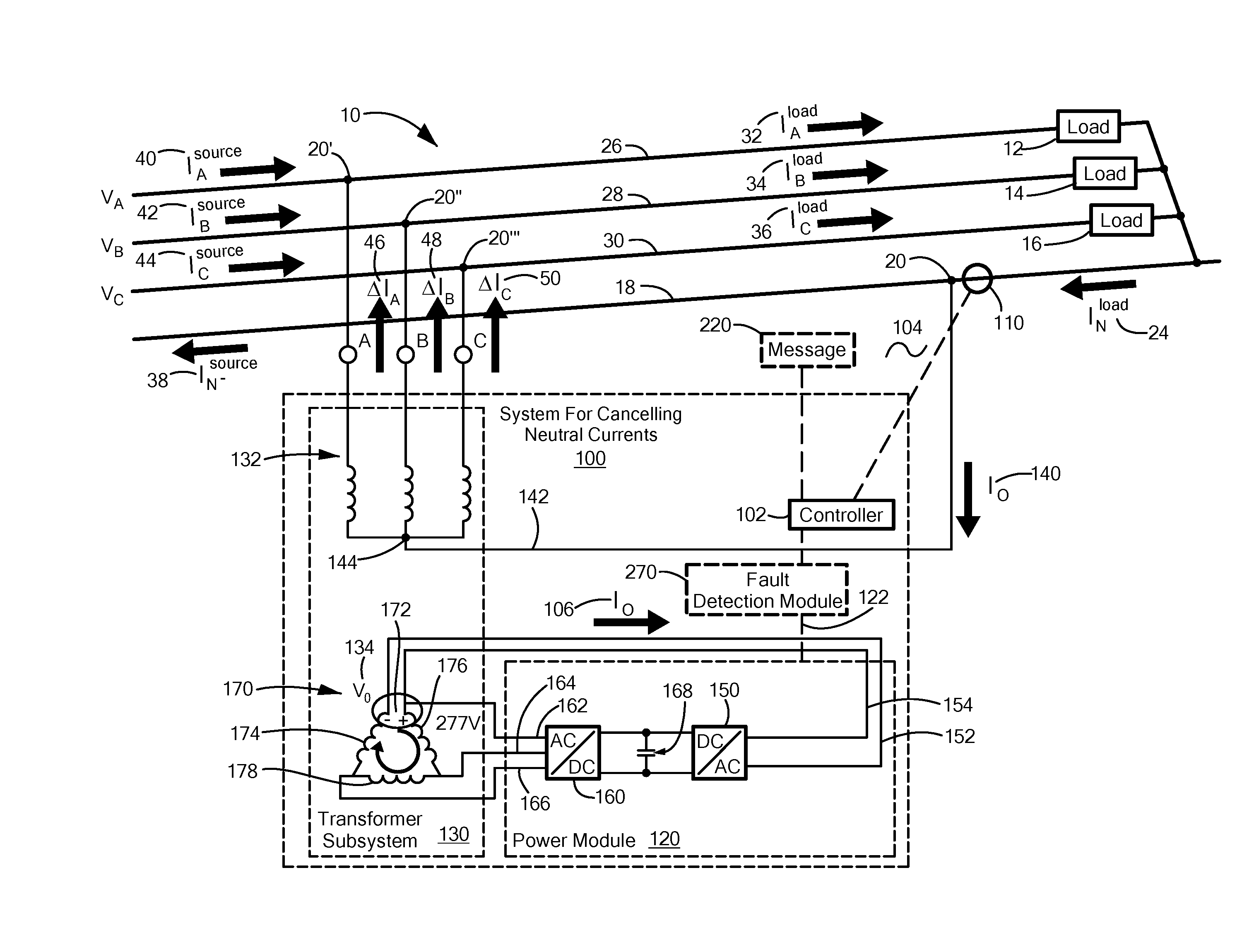
[0028]As discussed in the Background section above, multi-phase power distribution grid 10, FIG. 1, in this example, a three-phase, four wire power distribution grid, may become unbalanced due to load connections, e.g., at loads 12, 14, and 16. In this example, the loads 12, 14 and 16 are all single-phase loads and connect ...


PUM


Abstract

A system for cancelling fundamental neutral current on a multi-phase power distribution grid. The system includes a controller coupled to the power distribution grid responsive to a neutral current signal configured to determine a first corrective current based on at least the neutral current signal. A power module responsive to the controller is configured to generate the first corrective current. A transformer subsystem includes primary windings coupled to the power distribution grid and a zero sequence voltage point coupled to the power module. The transformer subsystem is configured to transform the first corrective current into a second corrective current coupled to the power distribution grid such that the second corrective current cancels all or part of a fundamental neutral current. The power module is configured as a four-quadrant power module which provides real power flow in either direction between the power module and the transformer subsystem at the zero sequence voltage point.

Description

RELATED APPLICATIONS[0001]This application claims benefit of and priority to U.S. Provisional Application Ser. No. 62 / 173,522 filed Jun. 10, 2015, under 35 U.S.C. §§119, 120, 363, 365, and 37 C.F.R. §1.55 and §1.78, which is incorporated herein by this reference.FIELD OF THE INVENTION[0002]This invention relates to a system for cancelling fundamental neutral current on a multi-phase power distribution grid.BACKGROUND OF THE INVENTION[0003]Multi-phase power distribution systems, such as a low or medium or high voltage three-phase power distribution grid, are often discussed in terms of being a “balanced” system or an “unbalanced” system. A system which is “balanced” has positive attributes both in its ability to be simply analyzed and in its physical characteristics. Conversely, an “unbalanced” system may be more difficult to analyze and may produce detrimental physical characteristics.[0004]One problem associated with an unbalanced multi-phase system is that current will flow in the...

Claims


Application Information

Patent Timeline
Patent Type & Authority Applications(United States)
IPC IPC(8): H02J3/01H02H7/28
CPCH02H7/28H02J3/01Y02E40/50H02J3/26
Inventor KAM, ANTHONYSIMONELLI, JAMES
Owner VARENTEC
Learn More