
Method for designing an ecs

a technology of ecs and design method, applied machines/engines, weight reduction, etc., can solve the problem of limited efficiency of engine fuel burn in the direction of energy-efficient board measures,

Active Publication Date: 2016-12-08
HAMILTON SUNDSTRAND CORP
View PDF27 Cites 6 Cited by
  • Summary
  • Abstract
  • Description
  • Claims
  • Application Information

AI Technical Summary

Benefits of technology

The patent text describes some new features and benefits that were made possible through certain techniques. These techniques are explained in detail in other parts of the patent and are considered part of the claims. Overall, the patent describes how these techniques can be used to achieve better understanding and improvement in certain aspects.

Problems solved by technology

Unfortunately, each of these approaches provides limited efficiency with respect to engine fuel burn.

Method used


Image

  • Method for designing an ecs
  • Method for designing an ecs
  • Method for designing an ecs

Examples


Embodiment Construction

[0015]A detailed description of one or more embodiments of the disclosed apparatus and method are presented herein by way of exemplification and not limitation with reference to the FIGS.

[0016]Embodiments herein provide a method of selecting a bleed port on an engine that is suitable to provide a medium for cabin pressurization at high fuel burn efficiency and an environmental control system to work with that bleed port. The medium can generally be air, while other examples include gases, liquids, fluidized solids, or slurries.

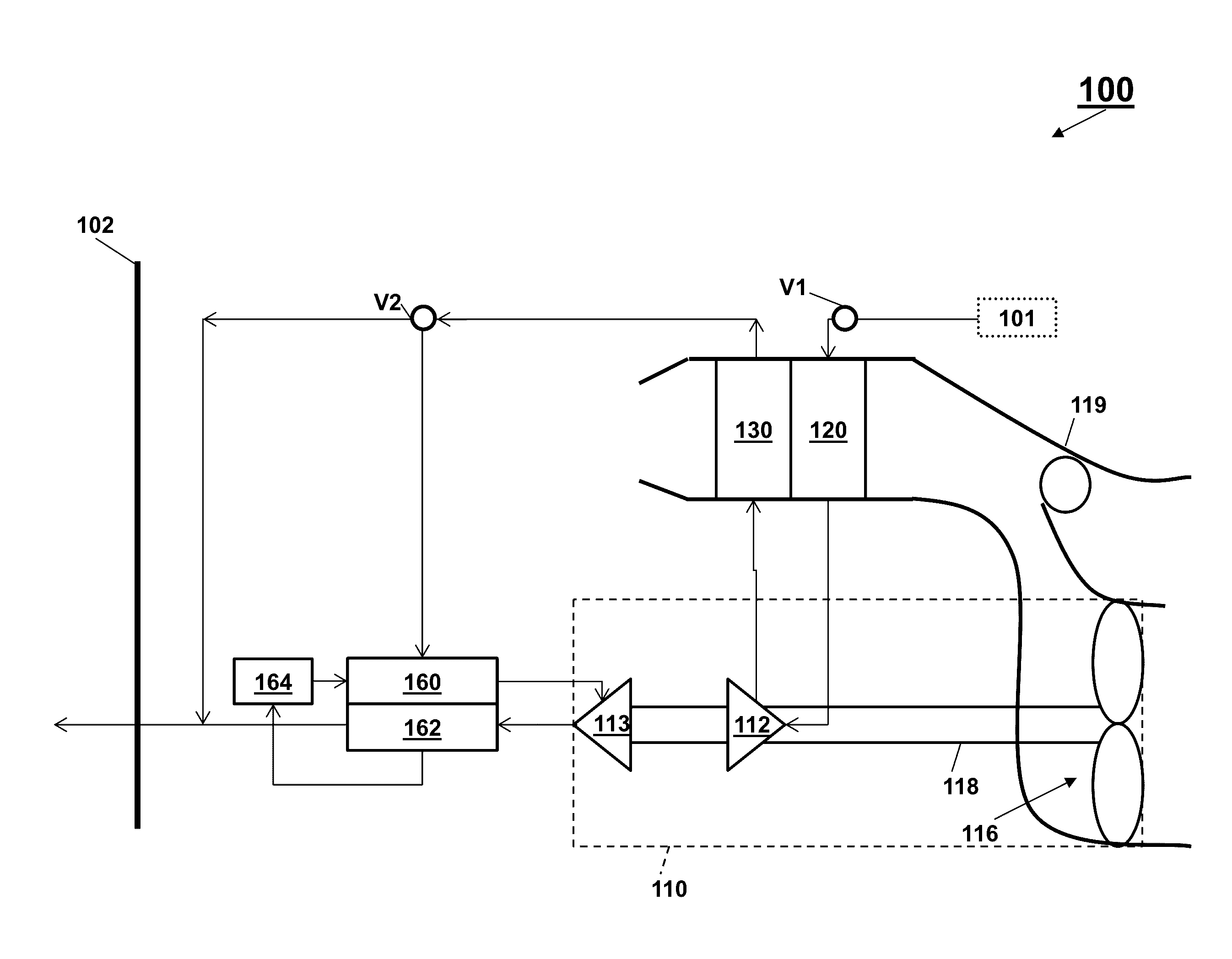
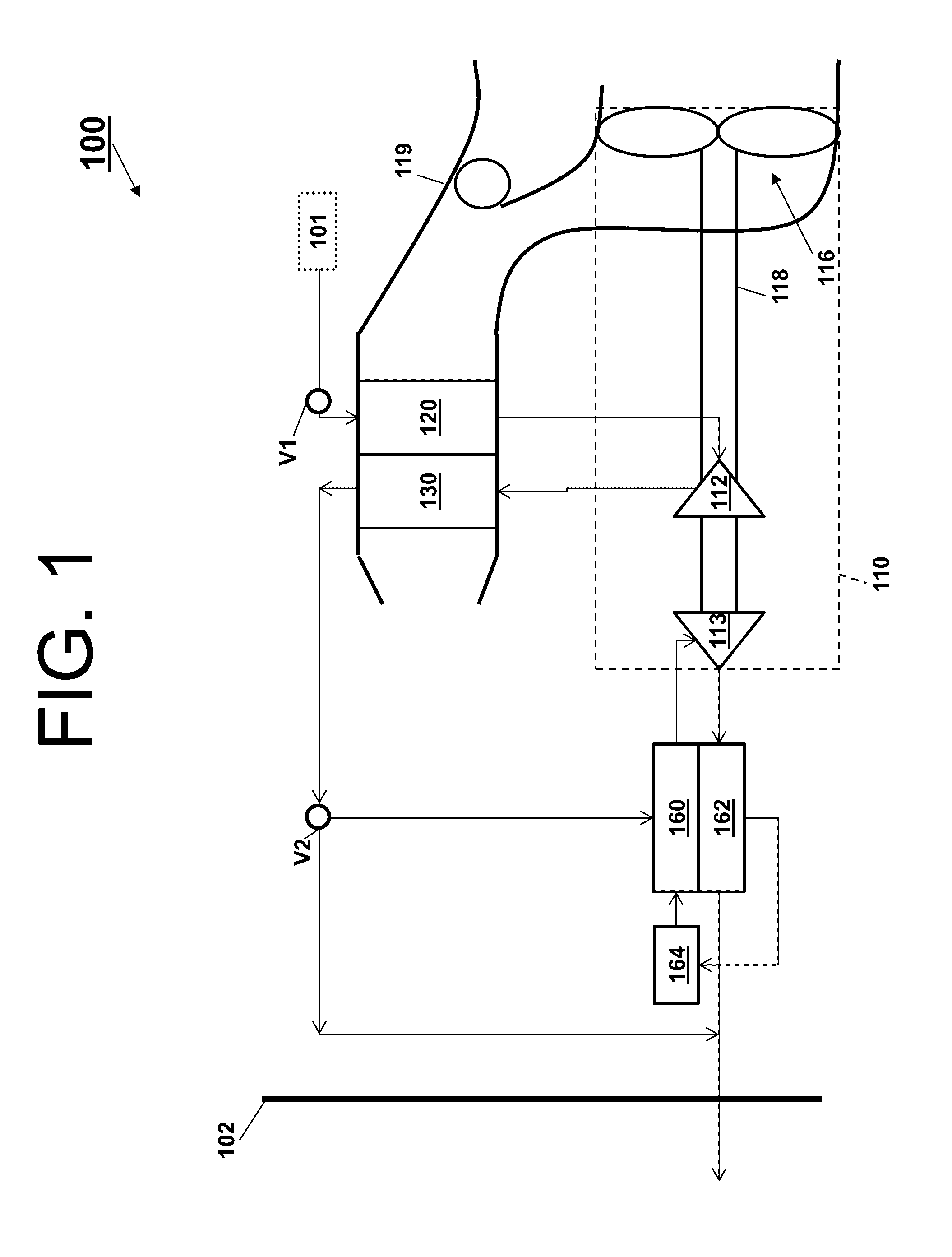
[0017]Turning to FIG. 1, a system 100 that receives a medium from an inlet 101 and provides a conditioned form of the medium to a chamber 102 is illustrated. The system 100 comprises a compressing device 110. As shown, the compressing device 110 comprises a compressor 112, a turbine 113, a fan 116, and a shaft 118. The system 100 also comprises a primary heat exchanger 120, a secondary heat exchanger 130, a reheater 160, a condenser 162, and a water extractor ...


PUM


Abstract

An airplane is provided. The airplane includes an environmental control system that provides a pressurized medium to a chamber of the airplane. The airplane also includes a bleed system. The bleed system includes a plurality of ports, each of which can provide a bleed medium from an engine of the airplane to the environmental control system. The plurality of ports includes at least a first port, a second port, and a third port. The first port is selected for an idle condition. The second port is selected for a hot day cruise condition. The third port is selected for a standard operating condition. The bleed system can operate in a first mode, a second mode, or a third mode to provide the bleed medium to the environmental control system from the first port, the second port, or the third port respectively.

Description

CROSS-REFERENCES TO RELATED APPLICATIONS[0001]This patent application claims priority to U.S. Provisional Patent Application Ser. No. 62 / 170,916, filed Jun. 4, 2015 which is incorporated herein by reference in its entirety.BACKGROUND[0002]In general, contemporary air condition systems are supplied a pressure at cruise that is approximately 30 psig to 35 psig. The trend in the aerospace industry today is towards systems with higher efficiency. One approach to improve airplane efficiency is to eliminate the bleed air entirely and use electrical power to compress outside air. A second approach is to use lower engine pressure. The third approach is to use the energy in the bleed air to compress outside air and bring it into the cabin. Unfortunately, each of these approaches provides limited efficiency with respect to engine fuel burn.BRIEF DESCRIPTION[0003]According to one embodiment, an airplane is provided. The airplane comprises an environmental control system configured to provide a...

Claims


Application Information

Patent Timeline
Patent Type & Authority Applications(United States)
IPC IPC(8): B64D13/06B64D13/08
CPCB64D13/06B64D2013/0644B64D2013/0618B64D13/08B64D13/02F02K3/00B64D2013/0611Y02T50/50Y02T50/40
Inventor BRUNO, LOUIS J.
Owner HAMILTON SUNDSTRAND CORP
Learn More