Motor acceleration methods

a technology of reluctance motors and acceleration methods, which is applied in the direction of ac motor acceleration/deceleration control, electric vehicles, electric devices, etc., can solve the problems of increasing the reluctance of magnetic circuits and magnetic energy, and the duration of the first step can be unacceptably long, so as to achieve constant timing, optimise torque, and reduce the effect of reluctan

Inactive Publication Date: 2016-11-17
VALEO AIR MANAGEMENT UK
View PDF2 Cites 2 Cited by
  • Summary
  • Abstract
  • Description
  • Claims
  • Application Information

AI Technical Summary

Benefits of technology

[0028]The acceleration according to the second aspect of the invention is particularly advantageous when the normal operation of the motor with all the coils is highly controlled using for example the look up table 41. These provide detailed values for the operational range of motor speeds. However for acceleration to those operational speeds, optimisation of torque, efficiency etc. is not needed and so the simple method of the invention may be used without having to engineer those details.
[0029]The pair of stator coils may be repeatedly turned on and off at a constant frequency (while keeping the other stator coil turned off). The timing at which the pair of stator coils are turned on and off is preferably independent of the desired torque and / or speed (torque / speed set-point). For example the timings are preferably not obtained from a look-up table. The timing may be constant. The timings may be in response to an output from a position sensor. For example the pair of stator coils is preferably turned on when the rotor is in a first position (preferably measured by the position sensor). The stator coils are preferably turned off when the rotor is in a second position (preferably measured by the position sensor). Such an arrangement is beneficial because it provides a simple way of accelerating the motor, without requiring a calculation, or other form of selection, of the timings.

Problems solved by technology

In a non-aligned position, e.g. as in FIG. 1A the magnetic flux still flows along the low reluctance path between the poles of rotor and so the flux is diverted from the diameter between the energised poles of the stator, with the result that it has to cross larger air gaps between the poles of the rotor and stator, increasing the reluctance of the magnetic circuit and the magnetic energy.
The known stating method described above has, however, the disadvantage that the duration of the first step be can be unacceptably long.

Method used


Image

  • Motor acceleration methods
  • Motor acceleration methods
  • Motor acceleration methods

Examples


Embodiment Construction

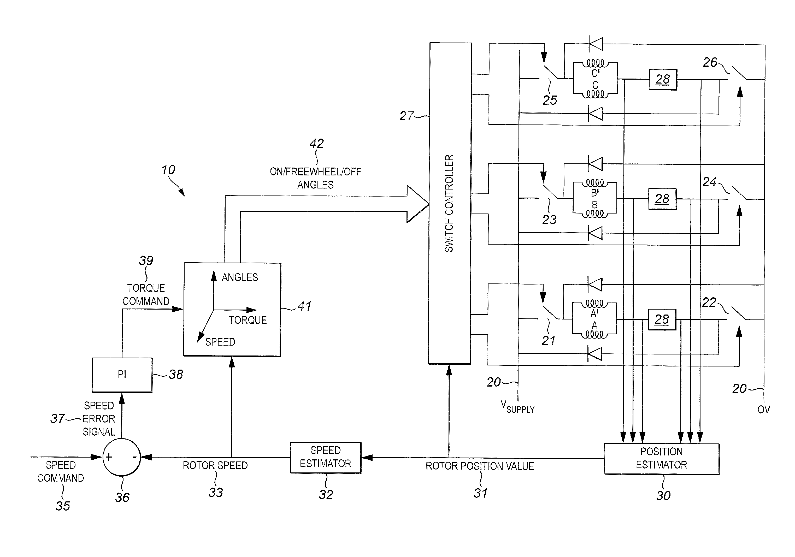
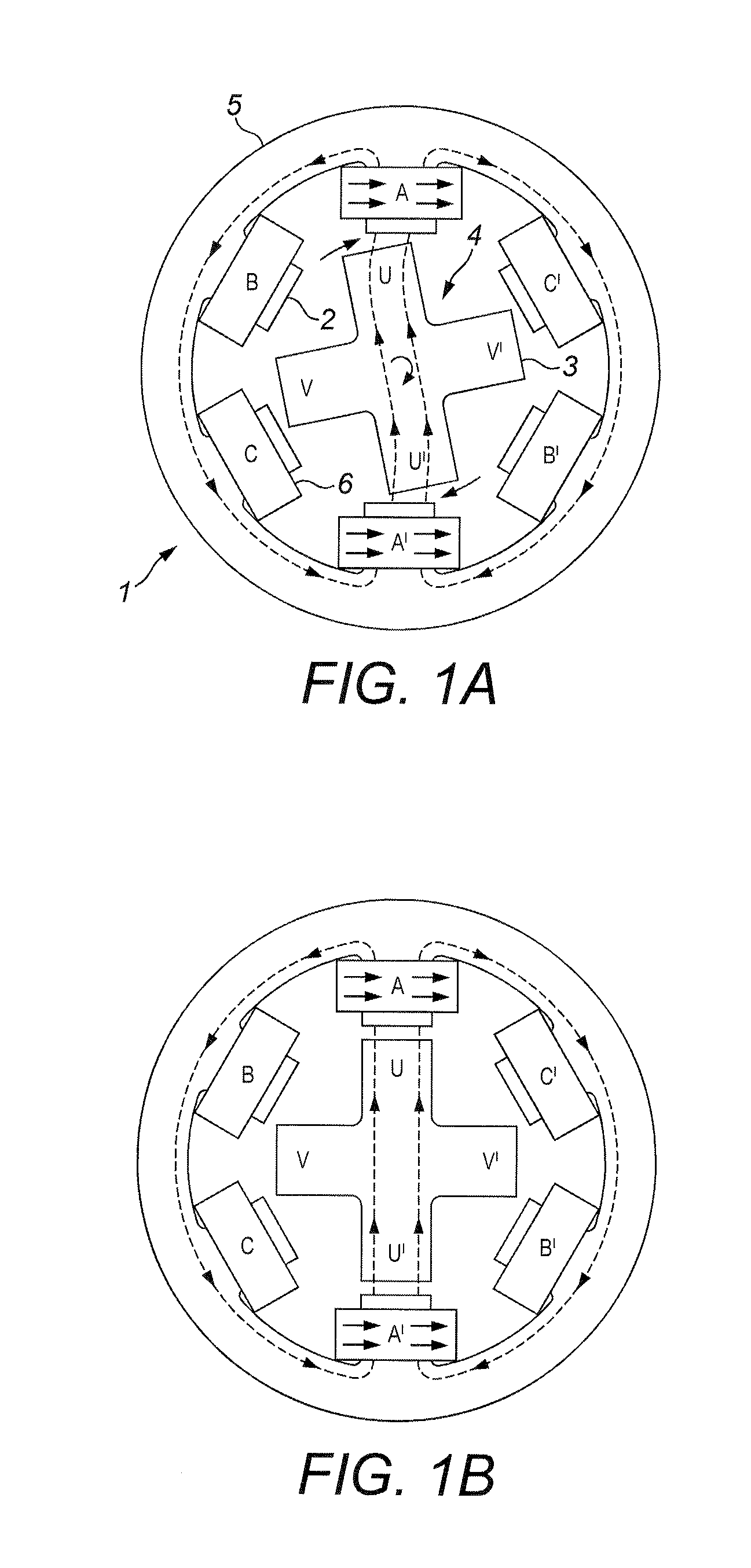
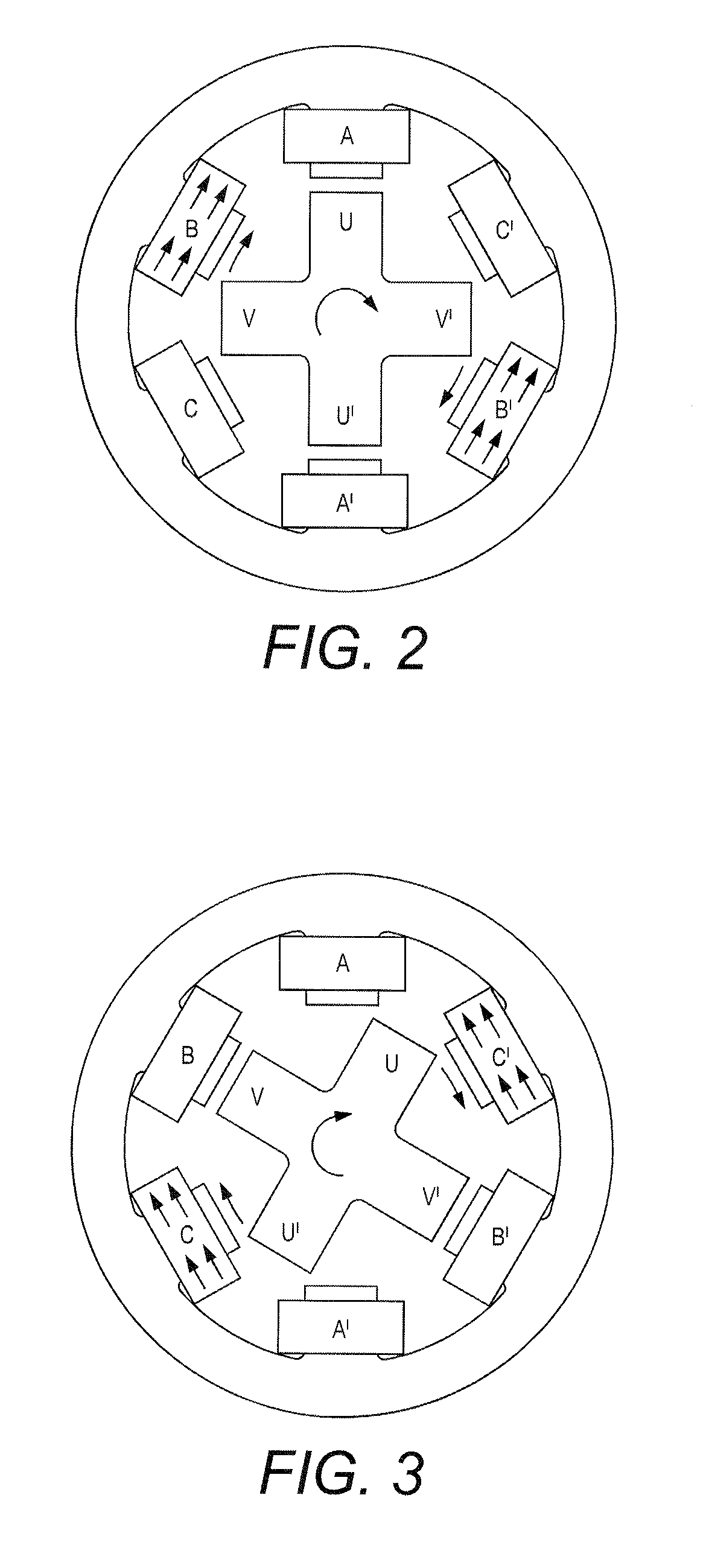
[0078]An exemplary method of starting a switched reluctance motor is shown in the flow diagram FIG. 12 and illustrated in FIGS. 9 to 11 which show stages of rotation of a switched reluctance motor. The motor in this example is similar to that of the FIGS. 1 to 8 having six stator poles and four rotor poles, which are similarly marked ABCA′B′C′ and UVU′V′. (ABCA′B′C′ denote equally the poles and their respective coils.) It is operated with a motor control circuit similar to that of FIG. 5 except the control circuit 10′(FIG. 13) is arranged to control the switches 21 to 26 to turn the coils of the motor on and off as described in this example. A start controller 50 (preferably implemented with an additional program in the microcontroller) is provided to do this.

[0079]The rotor begins in an arbitrary position, at which the rotor may be stationary or slowly moving, as shown in FIG. 9 (step 101, in FIG. 12) with all the coils off. In one such position, rotor pole U is between stator pole...


PUM


Abstract

An improved method of starting a switched reluctance motor uses two neighbouring pairs of coils, both energised, to bring the rotor to its initial position. Then one of pairs of coils is turned off and the rotor is attracted by the other pair of coils to give it an initial rotational speed. An intermediate stage uses just one pair of coils of the motor to bring it up to operational speeds, after which the normal cycling of all the coils can be used.

Description

FIELD OF THE INVENTION[0001]The present invention relates to switched reluctance motors and in particular to methods of starting such a motor.BACKGROUND[0002]A typical switched reluctance motor is shown in FIGS. 1A, 1B and 2 to 4. This example has a combination (which is frequent) of six, preferably evenly, spaced poles 2 on the stator 1 and four, preferably evenly, spaced poles 3 on the rotor 4. In this example, the poles of the stator project inwardly from a stator ring 5, the ring providing a path of low reluctance material between the stator poles.[0003]The rotor is formed of a stack of cross-shaped laminations, also of low reluctance material. Therefore each rotor pole is connected to the diametrically opposite rotor pole by a low reluctance path, for reasons which will become apparent. So, as marked, pole U is connected by a low reluctance path to pole U′ and pole V to pole V′.[0004]Each pole of the stator is wound with a coil 6 and the coils are arranged in pairs, each pair c...

Claims


Application Information

Patent Timeline
Patent Type & Authority Applications(United States)
IPC IPC(8): H02P23/20H02P1/16H02P25/08
CPCH02P23/20H02P1/163H02P25/08B60L2220/18H02P25/089H02P25/0925Y02T10/64
Inventor BOUALLAGA, KAMELDUPUIS, DOMINIQUE
Owner VALEO AIR MANAGEMENT UK
Why Eureka
Try Eureka