Printing apparatus

Active Publication Date: 2016-11-17
MIMAKI ENG
View PDF0 Cites 12 Cited by
  • Summary
  • Abstract
  • Description
  • Claims
  • Application Information

AI Technical Summary

Benefits of technology

The present invention provides a printing apparatus that can dry ink on an recording medium while preventing cockling from occurring. This is achieved by changing the flow direction of the preliminary air and directing it towards the gap between the recording medium and the cover member. By doing so, the uneven air flow and cockling are suppressed, allowing for efficient ink drying. Furthermore, the invention includes a heater that raises the temperature of the drying air flow, making it easy to manage the temperature during ink drying.

Problems solved by technology

However, in a case where ink is slowly dried, wet ink may be mixed, resulting in a decrease in chroma or blurring of images.
Especially, in printing apparatuses, such as line printers, which eject ink in units of lines extending in a main scan direction while conveying media, since the amount of ink ejection relative to the medium conveyance speed is large, it is difficult for ink to be dried.
However, warm air flows between an inkjet head and a medium, ink ejection positions on the medium may be deviated from predetermined positions, resulting in a degradation in the printing quality.
However, in a case of blowing warm air directly to a medium by a fan, so-called “cockling” which is a phenomenon that temperature on the medium becomes uneven, and this uneven temperature causes difference in drying time, whereby wrinkles are made in a wave shape in the medium may occur.
Also, in the case of blowing warm air directly to a medium, since temperature management is likely to be insufficiently performed, cockling may be caused by drying failure attributable to deficiency in the amount of heat or excessive heating.
Also, although it is preferable that the ink drying time should be very short, rapid drying which is performed by increasing the amount of warm air or raising the temperature of warm air, or uneven drying is likely to lead to occurrence of cockling.
As described above, it has been very difficult to dry ink ejected on media without causing cockling.
Also, since air blown from the air blower is directed downward, it is possible to make it difficult for heat generated by the heater to be transferred to the head.
Therefore, it becomes difficult for a recording medium to be suddenly deformed, and it is possible to effectively suppress cockling from occurring.

Method used


Image

  • Printing apparatus
  • Printing apparatus
  • Printing apparatus

Examples


embodiment

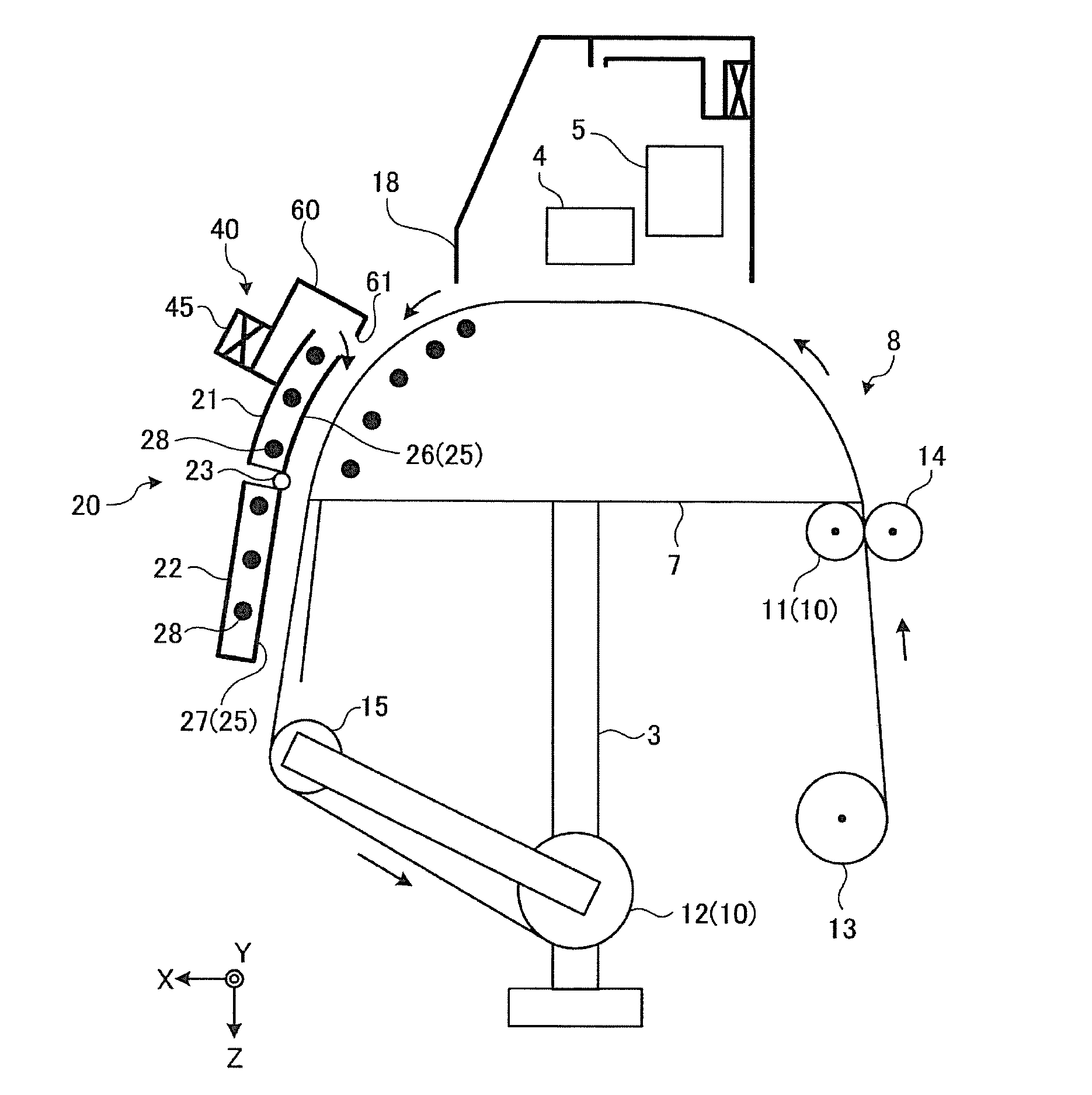
[0061]FIG. 1 is a perspective view of a printing apparatus of an embodiment. FIG. 2 is a schematic view illustrating the configuration of the printing apparatus shown in FIG. 1. A printing apparatus 1 according to the present embodiment is configured by assembling a dryer 20 with a printing apparatus main body 2, and the printing apparatus main body 2 includes: a head 4, a platen 7, and a driver 10. The printing apparatus main body 2 is supported by legs 3, which are placed at desired positions on the ground, whereby the printing apparatus main body 2 is installed at an arbitrary installation position. The head 4 included in the printing apparatus main body 2 is configured to be able to eject ink onto a medium 100 which is a recording medium when performing printing on the medium 100. The head 4 is configured to be able to eject ink while moving along a Y bar 5 extending in one direction, and the movement direction of the head 4 is a main scan direction (a Y direction in the drawing...


PUM


Abstract

A printing apparatus is provided and includes: a head that ejects ink onto a medium ; a driver that relatively moves the positions of the head and the medium; a cover member that is positioned on the downstream side from the head in the movement direction of the medium relative to the head, so as to cover at least a portion of the medium; an air blowing fan that sends a drying air flow for drying ink ejected on the medium, into a gap between the medium and the cover member; and a cord type heater that heats at least one of the drying air flow and a preliminary air which is the previous stage of the drying air flow. An air-flow-direction changing wall part is provided so as to change the flow direction of the preliminary air which is the previous stage of the drying air flow, at least once.

Description

CROSS REFERENCE TO RELATED APPLICATIONS[0001]This application claims the priority benefit of Japanese Patent Application No. 2015-100579, filed on May 15, 2015. The entirety of the above-mentioned patent application is hereby incorporated by reference herein and made a part of this specification.TECHNICAL FIELD[0002]The present disclosure relates to a printing apparatus.RELATED ART[0003]Printing apparatuses using inkjet heads jet ink from the inkjet heads onto media such as recording paper, thereby performing printing. However, in a case where ink is slowly dried, wet ink may be mixed, resulting in a decrease in chroma or blurring of images. Especially, in printing apparatuses, such as line printers, which eject ink in units of lines extending in a main scan direction while conveying media, since the amount of ink ejection relative to the medium conveyance speed is large, it is difficult for ink to be dried. For this reason, conventional printing apparatuses which positively dry ink...

Claims


Application Information

Patent Timeline
IPC IPC(8): B41J11/00
CPCB41J2/01B41J11/0015B41J11/0022
Inventor HARAYAMA, RYUTAAKUTA, SHUNSUKEYAMABE, KATSUTOSHIAMARI, TOMONORIFURUKAWA, YOSHIKAZUKAMIMURA, HIROKIKUDO, YUSAKU
Owner MIMAKI ENG
Why Eureka
Try Eureka