
Variable stiffness guidewire

a guidewire and variable stiffness technology, applied in the field of variable stiffness guidewires, can solve the problems of potentially difficult navigation, difficult to advance into the chosen vessel, difficult to place the guidewire into the vessel, etc., and achieve the effect of reducing or decreasing the stiffness of the guidewire, reducing or decreasing the stiffness, and being advantageous

Inactive Publication Date: 2016-11-17
LAKE REGION MFG
View PDF3 Cites 0 Cited by
  • Summary
  • Abstract
  • Description
  • Claims
  • Application Information

AI Technical Summary

Benefits of technology

[0006]By attaching a nitinol distal ground section to the stainless steel proximal core wire or element of a guidewire the propensity of the distal flexible section to bend and kink is reduced. This invention includes a highly torqueable, pushable guidewire with a relatively stiff proximal (preferably in one embodiment), stainless steel (SS) section and kink resistant nitinol medial to distal section attached to a shapeable SS, in one embodiment, (such as a SS ribbon) distal tip. The very distal SS tip will have the ability to be shaped by the end user in order to facilitate entry into the chosen vessels.
[0007]It is the purpose of this invention to provide an improved, kink resistant guidewire. This is best achieved by gradually decreasing the stiffness from the proximal to the distal end by using, for example, a combination of SS and variably heat-treated nitinol.
[0020]Stiffness is variable or is gradually decreased or decreasing by assembling a SS proximal section to a nitinol distal section, which is attached to an independent or attached SS tip. More specifically, the nitinol distal portion comprises a linear elastic nitinol proximal segment and a super elastic nitinol distal segment. The nitinol distal segment is attached to, e.g., an SS proximal portion or segment. This graduation from linear elastic nitinol to superelastic nitinol creates an advantageous, gradual, and controlled or controllable reduction or decrease in guidewire stiffness (in accordance with this invention) when moving distally from the proximal segment to the distal segment to create a kink resistant guidewire. The combination of this two-phase, distal nitinol section and the stiff proximal 304 stainless steel section along with the optional shapeable SS distal portion (i.e., a shaping ribbon) creates the ideal torqueable, pushable, and steerable guidewire having varying or distally-decreasing stiffness.

Problems solved by technology

This superelastic distal tip restricts shapeability and can cause the placement of the guidewire into a vessel to be difficult.
The shortcoming to a stainless steel distal section is that it can bend and kink during advancement, making it difficult to advance into the chosen vessel.
Current guidewires made of a SS proximal portion and superelastic nitinol distal portion have a transition in a step or discrete fashion, making for potentially difficult navigation.

Method used


Image

  • Variable stiffness guidewire
  • Variable stiffness guidewire
  • Variable stiffness guidewire

Examples


Embodiment Construction

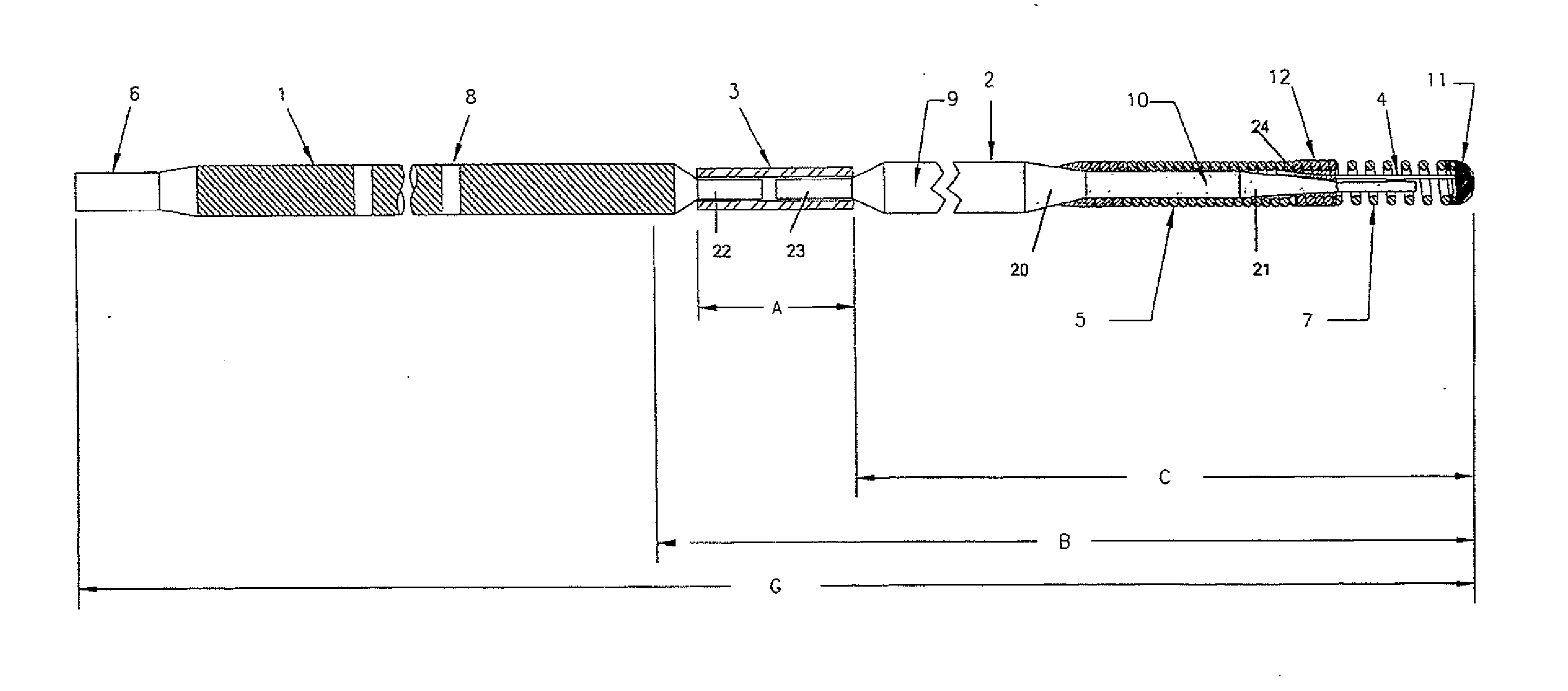
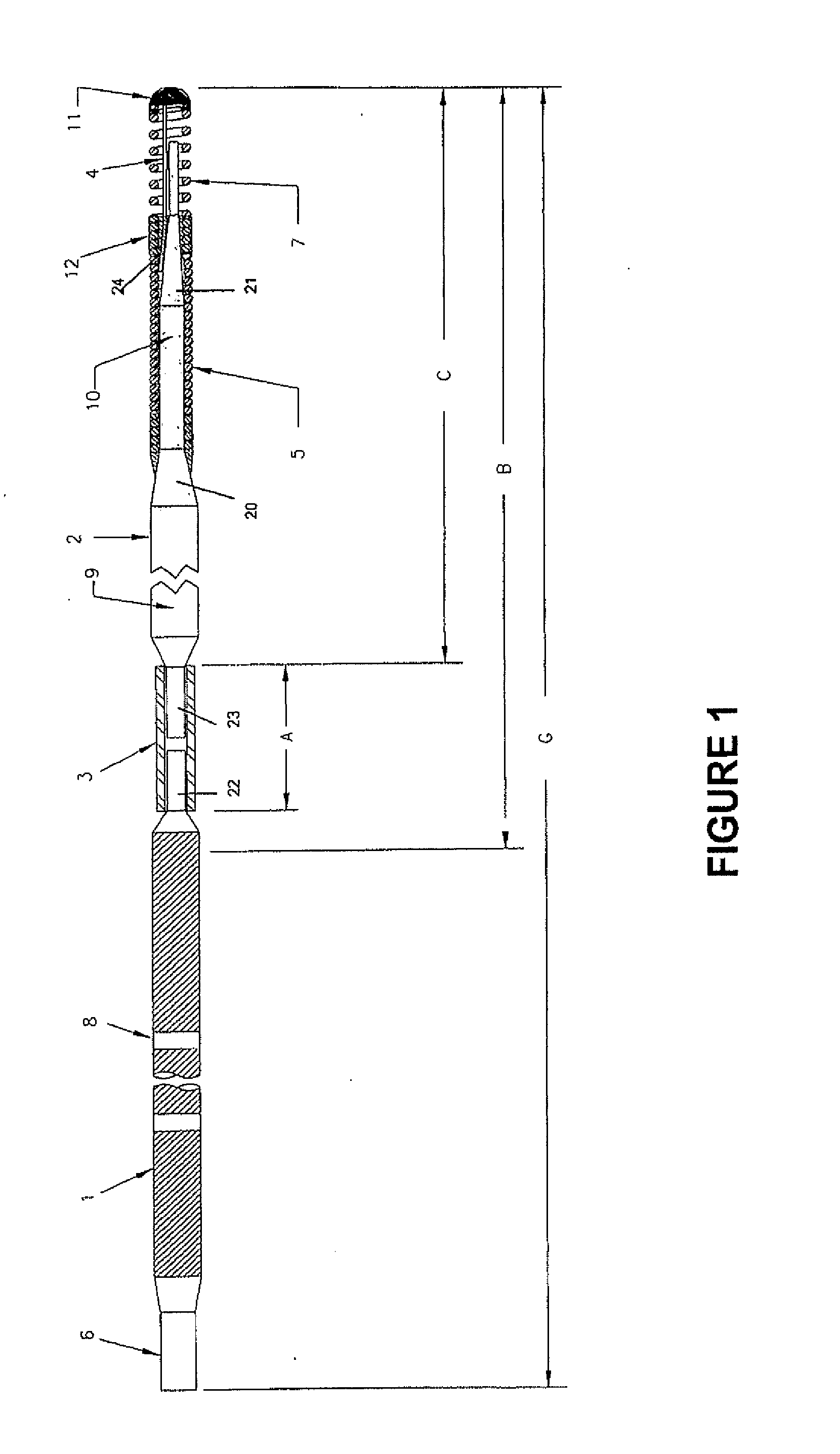
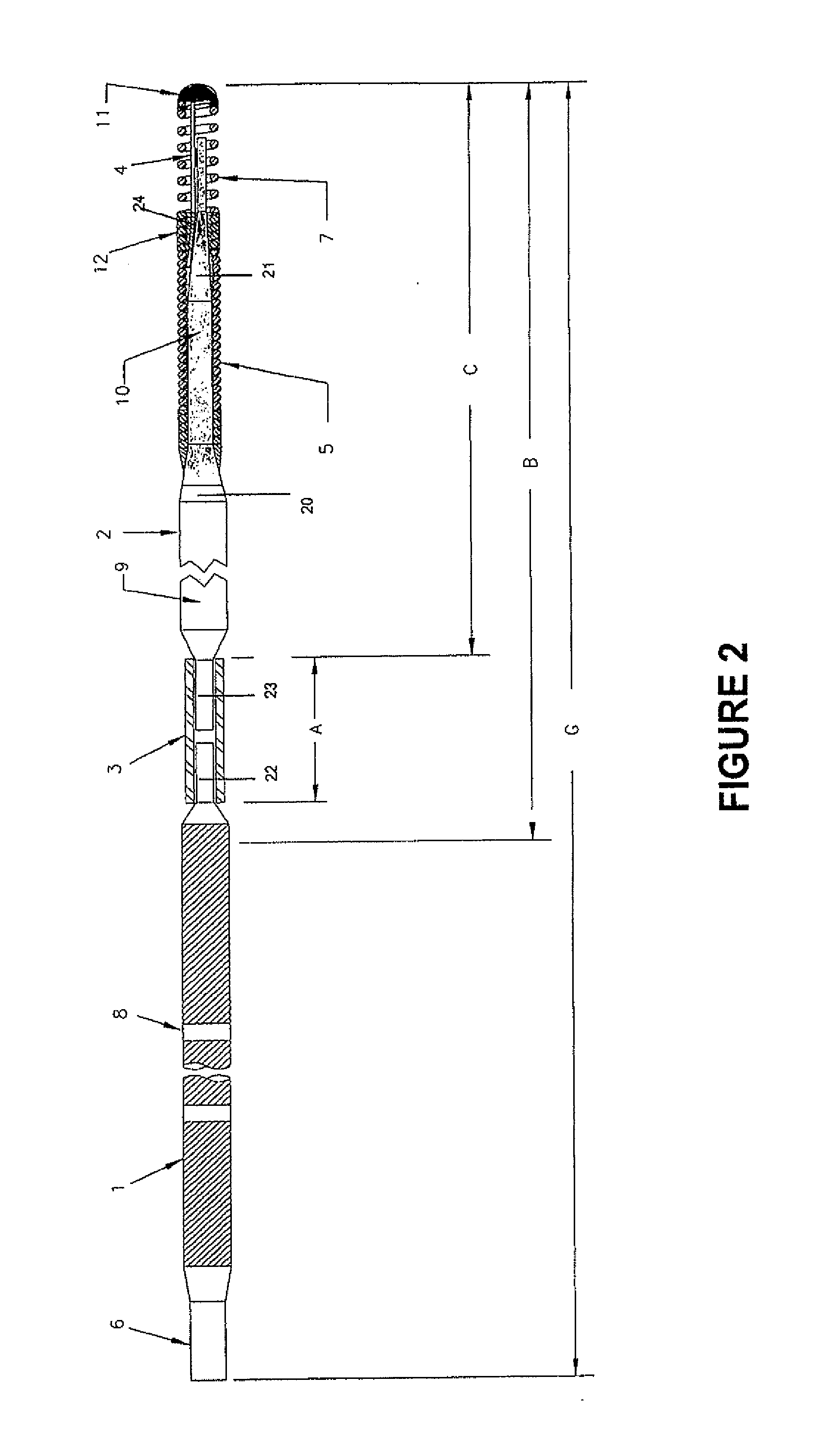
[0028]This invention is, in one embodiment, a Dual Phase Nitinol PTCA Guidewire (see attached FIGS. 1-7) with a stainless steel proximal shaft 1 and a nitinol medial to distal section 2 (generally, the length indicated by “C”) attached by a nitinol hypo tube 3. This nitinol middle section is then attached to a SS distal tip 11. Distal tip 11 is attached to the nitinol section 2 by means of a spring coil 5, 7 and a ribbon wire or safety ribbon 4. Spring coil 5, 7 comprises a radiopaque segment 7 and a non-radiopaque segment 5 which overlap or are interwound and are soldered together at 12. The embodiment shown has two tapered or ground section 20, 21. Other combinations of tapered, ground, or flattened guidewire sections are within the contemplation of this invention.

[0029]The invention encompasses a range of constructions from floppy to extra support grind configurations. The invention preferably is built in 190 cm length and 300 cm length configurations with a preferred maximum dia...


PUM


Abstract

This invention includes a highly torqueable, pushable guidewire with a relatively stiff proximal (preferably in one embodiment), stainless steel (SS) section and kink resistant nitinol medial to distal section attached to a shapeable SS, in one embodiment, (such as a SS ribbon) distal tip. The very distal SS tip will have the ability to be shaped by the end user in order to facilitate entry into the chosen vessels.

Description

CROSS-REFERENCE TO RELATED APPLICATIONS[0001]This application is a continuation of U.S. patent application Ser. No. 14 / 709,066, filed on May 11, 2015, which is a continuation of U.S. patent application Ser. No. 11 / 159,050, filed on Jun. 22, 2005, now abandoned, which claims priority to U.S. provisional patent application Ser. No. 60 / 582,033, filed on Jun. 22, 2004.BACKGROUND OF THE INVENTION[0002]In general, guidewires for medical procedures such as angioplasty, are made with stainless steel wire (SS) which, when ground in a series of tapers and straights, generally decreases from a proximal core body diameter of 0.014 inches down to a distal diameter of approximately 0.002 inches. A portion of this ground section of core, possibly including a ribbon wire, will be covered with one or more coils.[0003]Some disclosures describe guidewire with nitinol distal portions that yield at a desired set shape (U.S. Pat. No. 5,238,004) and consist of a SS proximal section attached to a linear el...

Claims


Application Information

Patent Timeline
Patent Type & Authority Applications(United States)
IPC IPC(8): A61M25/09A61M25/00
CPCA61M25/09A61M25/0054A61M25/09033A61M2025/09166A61M2025/09175A61M2025/09141A61M2025/0915A61M2025/09083A61B1/01A61M2025/09133
Inventor MINAR, CHRISDOUGLAS, JEANNESENN, ANDREW
Owner LAKE REGION MFG
Learn More