
Jamming detection method and device

a detection method and a technology for jamming, applied in the security sector, can solve the problems of reducing the signal to noise ratio of transmitted signals, disengaging the security system, and easy tampering of wired communications, and achieve the effect of complex input and output capabilities

Active Publication Date: 2016-11-10
VERISURE SARL
View PDF8 Cites 24 Cited by
  • Summary
  • Abstract
  • Description
  • Claims
  • Application Information

AI Technical Summary

Benefits of technology

This patent describes a device that detects when someone tries to jam communication between a security system and a base station. When this happens, an alarm is triggered. The device also allows users to send alarm messages at any time and ensures that the communication works properly. The device is designed to be resilient to jamming and can still operate normally without being affected. This makes the security system more secure and efficient.

Problems solved by technology

However, wired communications can be easily tampered, effectively disengaging the security system.
When this occurs, the wireless communication channel is actively interfered, reducing the signal to noise ratio of the transmitted signals and rendering communication impossible.
Although less likely, a similar scenario can occur as a result of unintentional interferences from nearby radio frequency systems.
However, modifying the frequency may not be enough to avoid the jamming.
Nevertheless, this approach could not be straightforwardly applied to wireless communication networks used in security systems such as Industrial Scientific and Medical (ISM) radio networks and Global System for Mobile Communications (GSM) networks.
Furthermore, the maximum achievable jamming protection is limited by the channel bandwidth of the architecture of the network used for the communication link, which could prove insufficient in some scenarios.
Furthermore, by using a fixed frequency in each station, the system is more predictable and easily tampered, and it requires significant resources to be employed in calibration and frequency drift corrections.

Method used


Image

  • Jamming detection method and device
  • Jamming detection method and device
  • Jamming detection method and device

Examples


Embodiment Construction

[0033]The matters defined in this detailed description are provided to assist in a comprehensive understanding of the invention. Accordingly, those of ordinary skill in the art will recognize that variation changes and modifications of the embodiments described herein can be made without departing from the scope and spirit of the invention. In particular, note that any particular embodiment or feature of the device of the invention may be applied to the method of the invention and vice versa. Also, description of well-known functions and elements are omitted for clarity and conciseness.

[0034]In this text, the term “ultra narrow band network” refers to any wireless network in which the spectrum of a transmitted signal is confined to a small spectral range, being said spectral range actively limited through signal modulation and / or signal processing techniques. The ultra narrow band network is therefore a network with a narrower transmission bandwidth and increased resistance against ...


PUM


Abstract

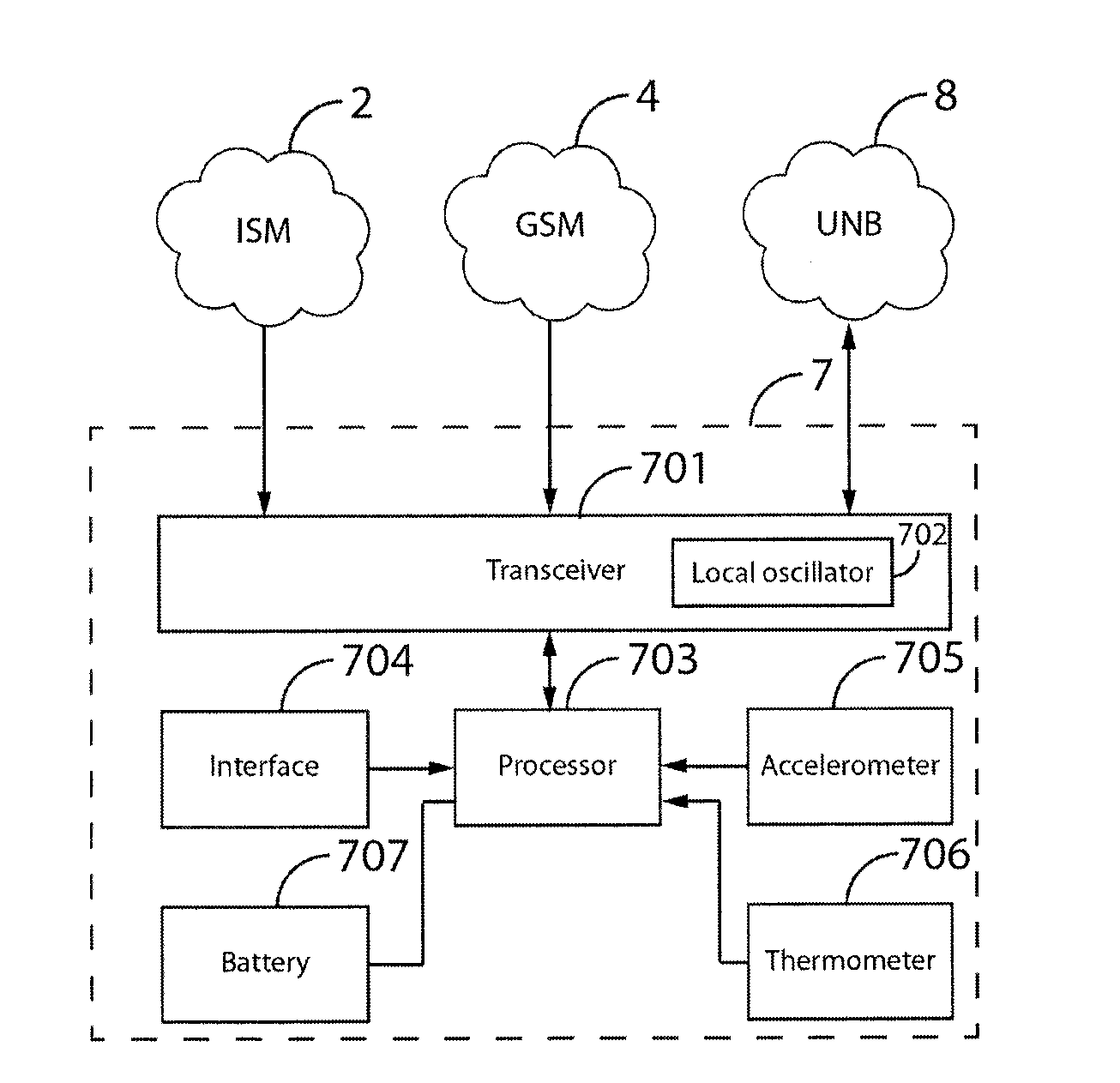
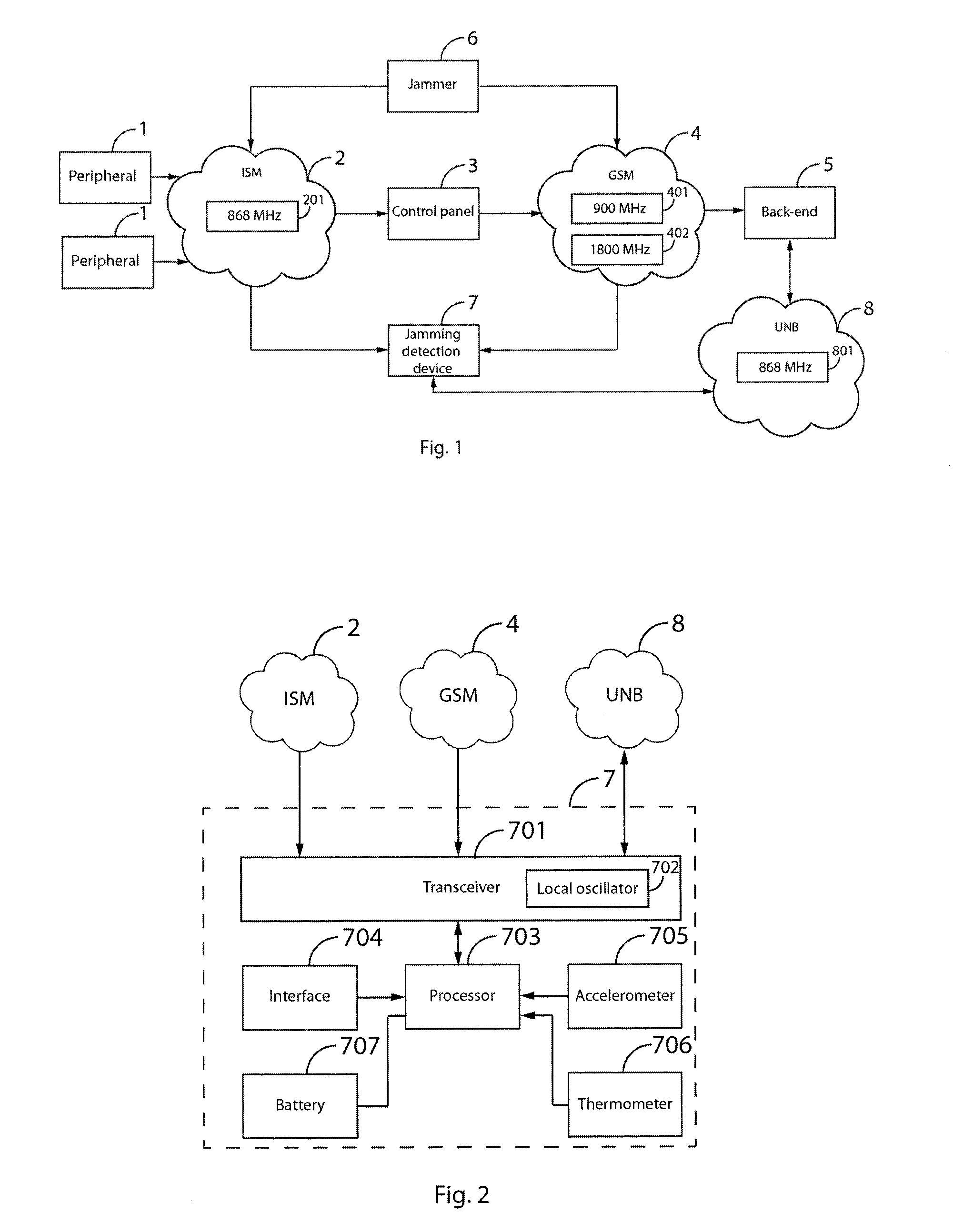
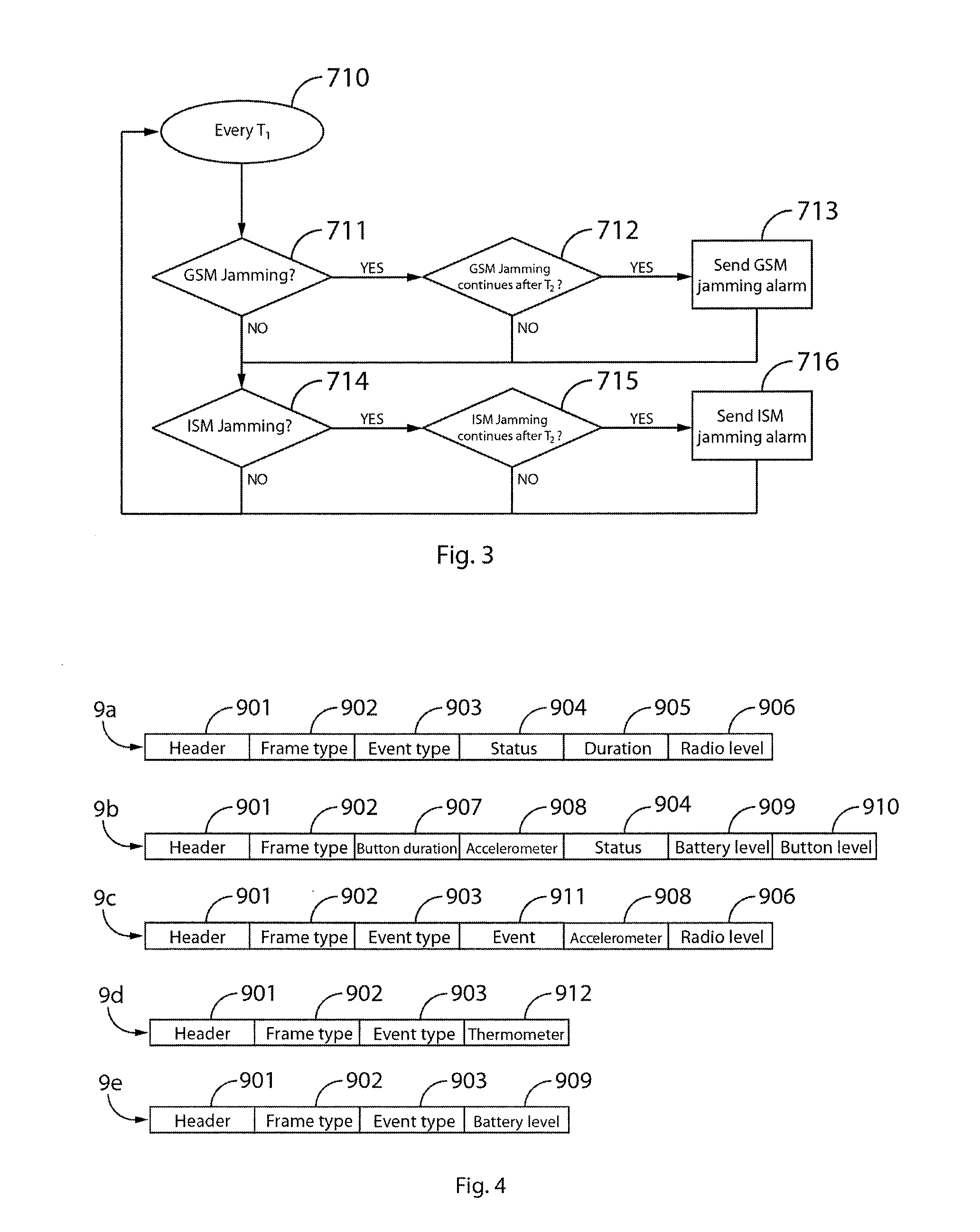
Jamming detection device (7) and method, which scan one or more frequency bands (201, 401, 402) and, if jamming is detected in said frequency bands (201, 401, 402), transmits an alarm signal through an ultra narrow band network (8). Preferably, both an ISM network (2) connecting a control panel (3) and at least one peripheral (1), and a GSM network (4) connecting the control panel (3) and a back end service (5), are scanned. Also preferably, the ultra narrow band network (8) is implemented over the same frequency band (801) as the ISM network (2) connecting the control panel (3) and the least one peripheral (1).

Description

FIELD OF THE INVENTION[0001]The present invention has its application within the security sector and, especially, in the industrial area engaged in providing intruder and theft alarms.BACKGROUND OF THE INVENTION[0002]Modern security and surveillance systems, such as those providing intruder or burglar alarms, typically comprise a central control panel connected to a plurality of peripherals such as video cameras, microphones, pressure sensors, temperature sensors, movement detectors, etc. When a possible threat is detected by any of the peripherals, said peripheral alerts the central control panel, which in turn transmits an alert signal to a remote centralized back-end service. Communications between peripherals and control panel, and between control panel and back-end services can be performed either through wired or through wireless communication systems. However, wired communications can be easily tampered, effectively disengaging the security system. Wireless communications are...

Claims


Application Information

Patent Timeline
Patent Type & Authority Applications(United States)
IPC IPC(8): H04L12/24H04L12/26H04W72/04
CPCH04L41/0631H04L43/16H04W72/0453G08B29/046G08B29/08H04K3/22G08B25/10G08B26/007G08B29/123
Inventor NORDMARK, PER LARSPIORNO IGLESIAS, ANGELNOBLE ECHEVERRIA, JON
Owner VERISURE SARL
Learn More