
Reversible electrical machine for an aircraft

a rotary wing aircraft and electrical machine technology, applied in the field of electric machines, can solve the problems of requiring maintenance on the electrical machine more frequently, affecting efficiency, and affecting the operation of the electric machin

Inactive Publication Date: 2016-11-10
EUROCOPTER
View PDF3 Cites 18 Cited by
  • Summary
  • Abstract
  • Description
  • Claims
  • Application Information

AI Technical Summary

Benefits of technology

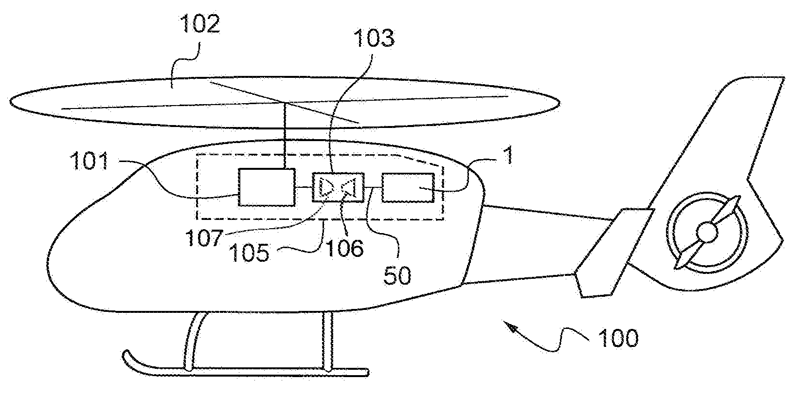
The present invention proposes a reversible electrical machine that can rotate an aircraft's main rotor and also convert some of the mechanical energy from the rotor into electrical energy. This machine aims to overcome the problems of previous generations.

Problems solved by technology

A main drawback of such a DC electrical machine lies in the electrical contacts needed between the rotor coils and the rotary commutator.
These contacts, e.g. obtained by brushes, can give rise to electric arcs leading in particular to wear and to interference, and consequently requiring maintenance to be performed on the electrical machine more frequently.
In addition, electric motors of that type are not suitable for high speeds of rotation and they consume energy in friction, thereby degrading efficiency.
Finally, they can be complex to make.
When the coils of the stator carry AC, they create one or more rotating stator magnetic fields that cause rotor electric current to appear in the rotor coils, thereby generating magnetic torque on the rotor, and consequently causing the rotor to rotate relative to the stator.
Conversely, rotation of the rotor as generated by external mechanical power will lead to the appearance of AC flowing in the coils of the stator.
If all of the power in generator mode is not used, that leads to high levels of losses by the Joule effect and to a degradation in terms of efficiency and in terms of the power per unit weight of the machine, in particular because of the need to add a large system for dissipating the heat generated by the Joule effect.
Furthermore, a short circuit on one or more coils of the stator, and consequently on one or more phases of the stator, can give rise to a high level of opposing torque that can lead to a rapid loss in the speed of rotation of a reversible electrical machine.
This braking of the rotation of the electrical machine can have severe consequences, e.g. on a transmission member that is mechanically coupled to the outlet shaft of the electrical machine.
Finally, during rotation of the rotor, a short circuit on one or more coils of the stator can give rise to high induced currents in each short-circuited coil, and that can lead to local heating of the coil that might cause a fire.
Although reversible, that type of electrical machine therefore does not make it possible to achieve performance levels that are equivalent both in motor mode and in generator mode if there is unbalance in terms of demand between those two modes.
Consequently, a sufficiently high safety level is not achievable for incorporating such a reversible electrical machine with permanent magnets in a rotary wing aircraft, for example.
Nevertheless, such electrical machines present lower performance in motor mode than can be achieved in machines using permanent magnets.
Nevertheless, various constraints of such electrical machines limit their applications.
Firstly, for a rotary wing aircraft, the reversible electrical machine may be connected mechanically to the MGB or to the compressor of a turboshaft engine, and the torque requirement of the electrical machine in motor mode is large.
However, as mentioned above, this torque requirement is prejudicial to the performance of such an electrical machine in generator mode since the electrical power demand in generator mode is much less than the mechanical power demand in motor mode, or else it is necessary to use electrical machines that are heavy and bulky, and in particular that include large cooling systems.
Furthermore, in the event of a short circuit on at least one coil of one of those electrical machines, high levels of damage can be generated, in particular in the MGB of the aircraft and in the environment surrounding the electrical machine.
Consequently, such a fuse section is difficult to install, since the resisting torque from the electrical machine and the torque delivered by the electrical machine in motor mode may be equivalent.
However, such a machine then has dimensions and weight that are not favorable for use on board a rotary wing aircraft.
That type of connection makes it possible to avoid damaging the MGB in the event of such a short circuit, but it prevents the electrical machine from being used in reversible manner, thereby losing its generator function.

Method used


Image

  • Reversible electrical machine for an aircraft
  • Reversible electrical machine for an aircraft
  • Reversible electrical machine for an aircraft

Examples


Embodiment Construction

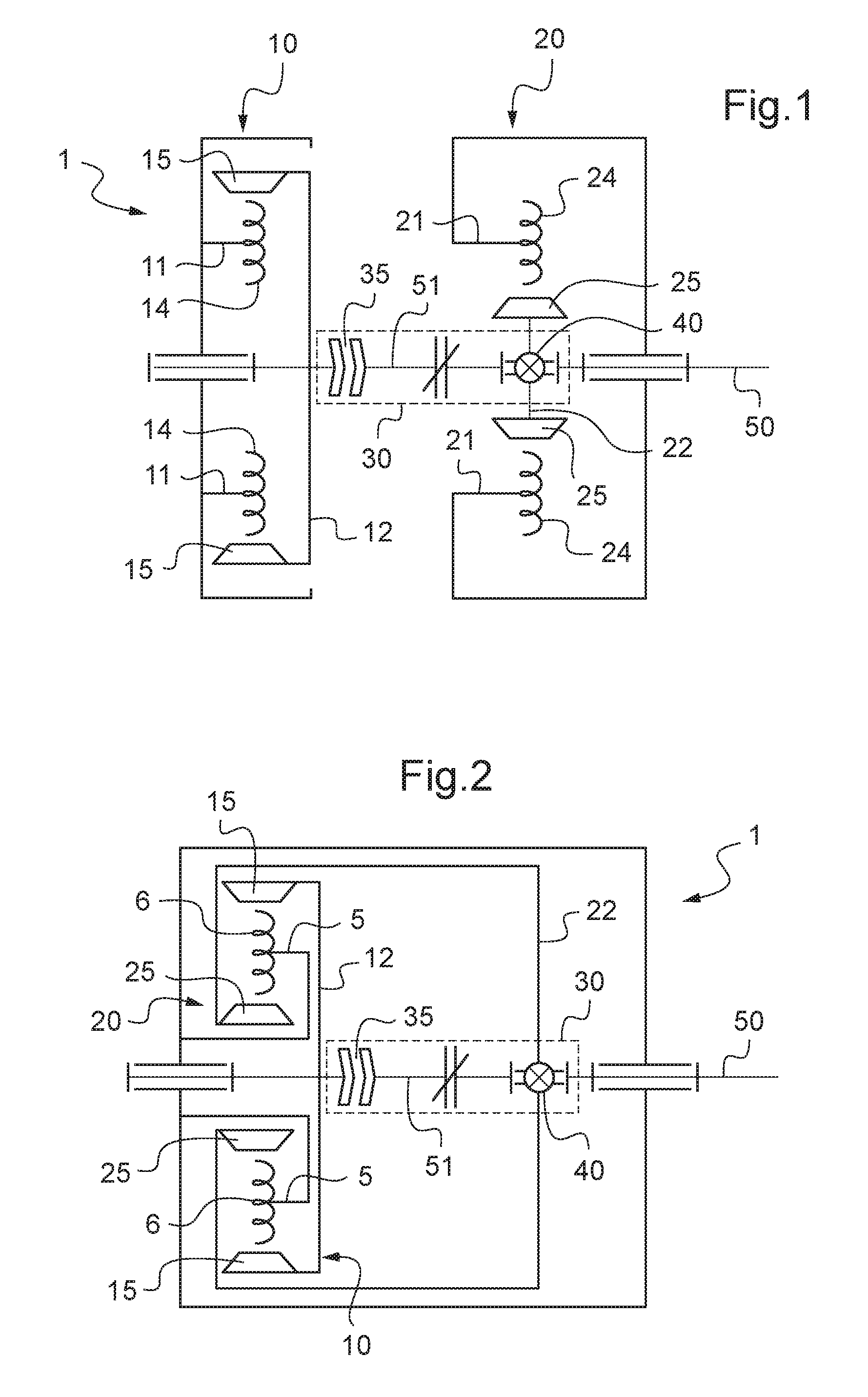
[0108]FIG. 1 shows an embodiment of a reversible electrical machine 1 of the invention having a first electrical device 10, a second electrical device 20, first disengageable coupling means 30, and an outlet shaft 50. The first device 10 is a motor and has a first rotor 12 co-operating with a first stator 11. Likewise, the second device 20 has a second rotor 22 co-operating with a second stator 21, however this second device is a motor-generator. Each stator 11, 21 is provided with non-permanent magnets 14, 24 made up of one or more windings of conductor wires serving to generate at least one stator magnetic field when passing an electric current. Each rotor 12, 22 is provided with permanent magnets 15, 25 generating respective first and second rotor magnetic fields.

[0109]In FIG. 1, as in all of the figures, the non-permanent magnets 14, 24 and the permanent magnets 15, 25 are oriented radially relative to the axis of rotation of each rotor 12, 22, thus enabling the magnetic flux to...


PUM


Abstract

A reversible electrical machine (1) comprising: a first electrical device (10) having a first stator (11) and a first rotor (12); a second electrical device (20) including a second rotor (22) and a second stator (21) together with an outlet shaft (50) and first disengageable coupling means (30) enabling said first and second rotors (12, 22) to be associated and dissociated in rotation. Said reversible electrical machine (1) also includes second disengageable coupling means (40) that are disengageable under a predetermined force and that mechanically connect said second rotor (22) to said outlet shaft (50). Said first electrical device (10) is a motor for transmitting high mechanical power to said outlet shaft (50), while said second electrical device (20) is a motor-generator for operating in motor mode to transmit additional mechanical power to said outlet shaft (50), and in generator mode for receiving mechanical power from said outlet shaft (50).

Description

CROSS REFERENCE TO RELATED APPLICATIONS[0001]This application is a continuation of U.S. application Ser. No. 13 / 945,326, filed Jul. 18, 2013, which claims priority to French patent application No. FR 12 02056 filed on Jul. 19, 2012, the disclosure of which are incorporated in their entirety by reference herein.BACKGROUND OF THE INVENTION[0002](1) Field of the Invention[0003]The present invention relates to the field of electrical machines. It relates to a reversible electrical machine, i.e. an electrical machine that may act as a motor or as a generator. The invention relates more particularly to a reversible electrical machine for a rotary wing aircraft, and also to a power plant for such an aircraft.[0004](2) Description of Related Art[0005]An electrical machine is said to be “reversible” when it makes it possible both to transform electrical energy into mechanical energy and also to transform mechanical energy into electrical energy.[0006]An electrical machine transforming electr...

Claims


Application Information

Patent Timeline
Patent Type & Authority Applications(United States)
IPC IPC(8): H02K7/18B60L11/12B64D35/02B64C27/14B64D27/24H02K7/00H02K16/00B60L50/15
CPCH02K7/1823H02K7/006B60L11/12H02K16/00B64D2027/026B64D27/24B64D35/02B60L2200/10B64C27/14H02K7/108H02K16/02Y02E20/16B60L2220/42B60L50/15Y02T10/64Y02T10/7072Y02T50/60B64D27/026
Inventor MARIOTTO, DAMIEN
Owner EUROCOPTER
Learn More